CM602all_EJM8AESM_Service Manual.pdf - 第634页
Machinery Part Replacement Remark Item 12-Nozzle Head Unit Nozzle θ ad j ustment Jig Mount the head. 16 See "12-Nozzle-Head-Unit Replacement." Section 5-10-1 15 Holding setscrew x 2 Ji g 1. Mount the nozzle hol…
Machinery Part Replacement
Remark
Item
12-Nozzle Head Unit
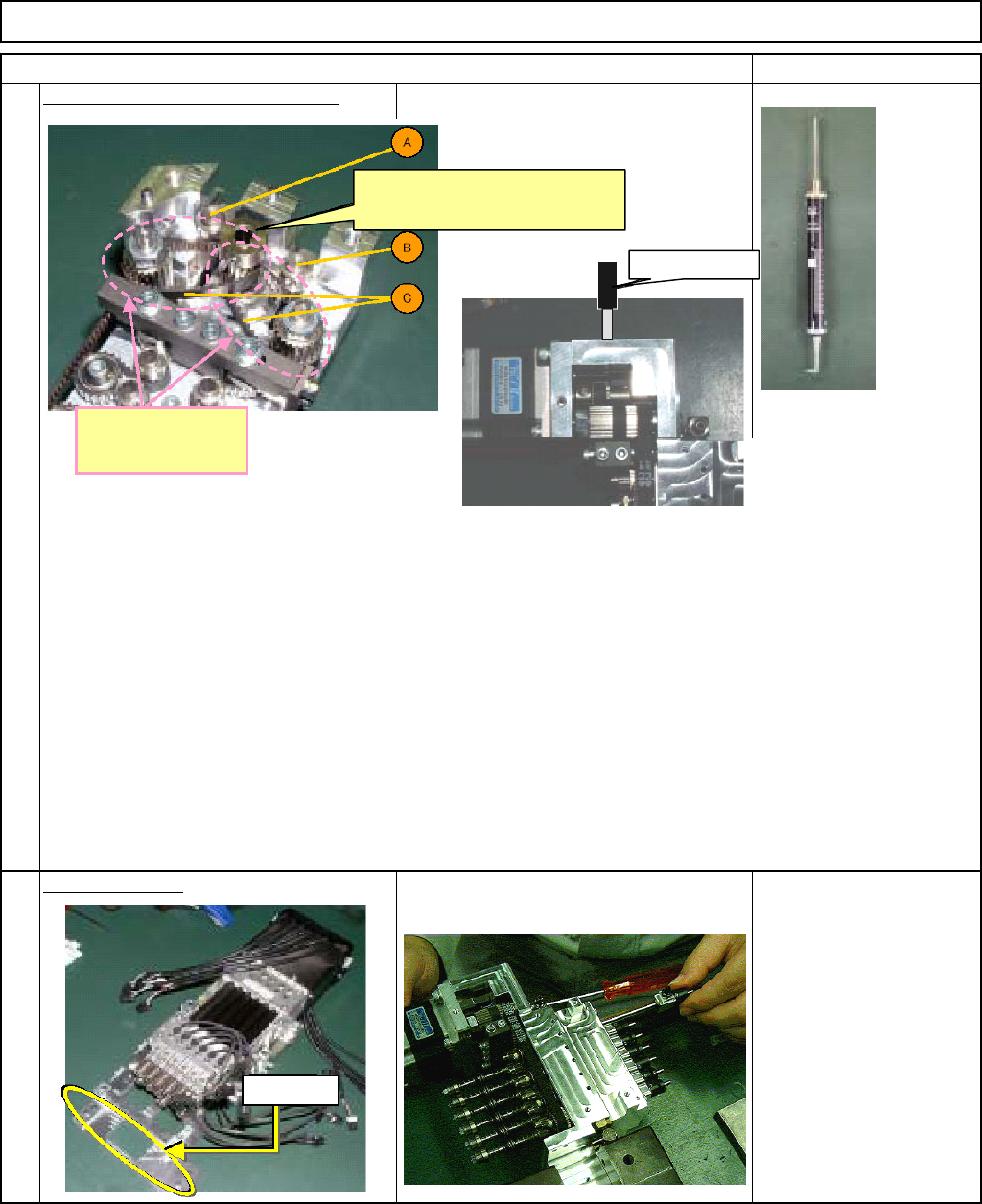
Adjust the tension of the short belt.
Install the θ-unit.
14
See "θ-Unit Removal."
Section 5-10-8
13
A
djust the tension o
f
the two belts.
This pulley should be connected
with the θ-axis motor.
Tension gauge
How to adjust the tension of the short belt (two belts)
1. Loosen the tension-adjuster-holding bolt.
Loosen the bolt for the section to be adjusted. Do not loosen the two bolts at the same time.
2. With 18.5 +/- 1.5N-pressure applied to one belt with tension gauge, rotate the θ-axis motor five
turns manually, and tighten the tension-adjuster-holding bolt.
With 10-N tension applied to the belt, fix the tension adjuster.
However, to release the excessive tension applied, rotate the θ-axis motor approximately five turns.
3. Repeat the procedures for the other belt.
Dowel pin
EJM8A-E-SMA051005-A01-00
Page 5-10-5-7
Machinery Part Replacement
Remark
Item
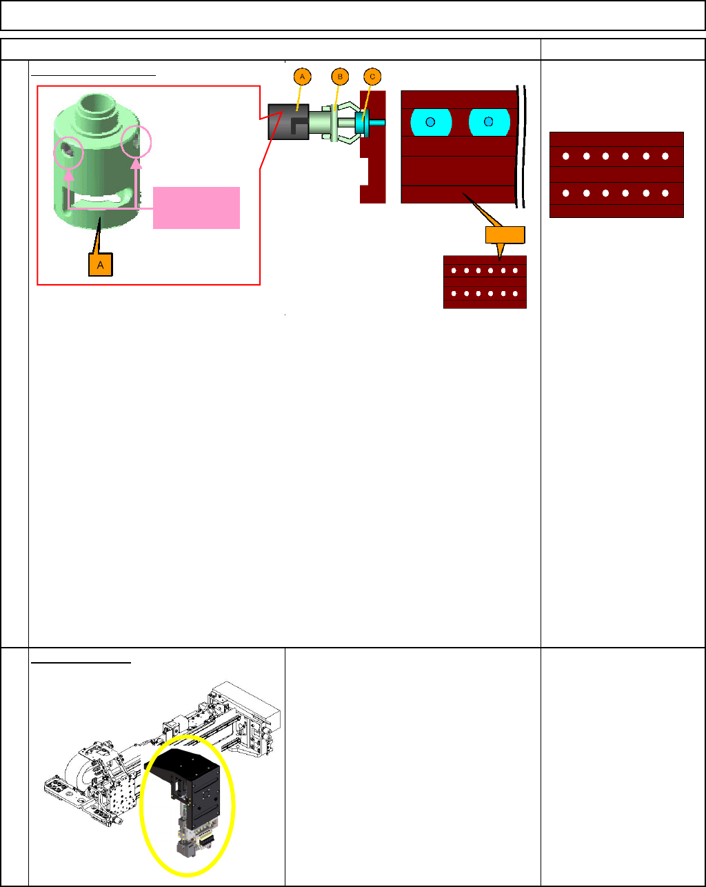
12-Nozzle Head Unit
Nozzle θ ad
j
ustment
Jig
Mount the head.
16
See "12-Nozzle-Head-Unit
Replacement."
Section 5-10-1
15
Holding
setscrew x 2
Ji
g
1. Mount the nozzle holder (B) onto the holder (A).
2. Fit the nozzles (C) onto the nozzle holder (B).
3. Loosen the holder (A)-holding setscrews.
Loosen the two setscrews on each position of A so that the nozzle can be rotated.
4. Adjust the nozzles (Cs: 1 to 6 and 7 to 12) with the jig, and tighten the holding setscrews.
Adjust 1 to 6 first, and then adjust 7 to 12 with 1 to 6 kept adjusted.
Adjust the direction of Cs with the jig.
5. Once 1 to 6 and 7 to 12 have been adjusted, check the jig can be set correctly.
* If adjustment fails, the jig cannot be set.
EJM8A-E-SMA051005-A01-00
Page 5-10-5-8
Machinery Part Replacement
Remark
Item
12-Nozzle Head Unit
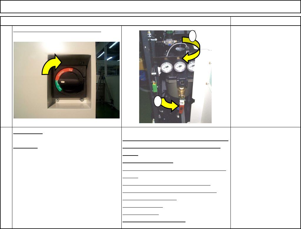
Turn off the power and air supply.
0.49MPa to
0.54MPa
A
d
j
ustment
Teaching
Head Camera Adjustment (Focus and q)
Board Recognition Camera XY Origin
Offset
Z-axis Origin Offset
Chip Recognition Camera, θ-axis Origin
Offset
Width Adjusting-axis Origin Offset
Mount Height and Board Positioning
XY Plane Calibration
Pickup Position
Light Intensity
Nozzle Change Position
M
ou
n
t
P
os
i
t
i
o
n
Section 5-11-1
Section 5-11-2
Section 5-11-3
Section .5-11-4
Section 5-11-5
Section 5-11-6
Section 5-11-7
Section 5-11-8
Section 5-11-9
Section 5-11-10
Section 5-11-11
17
18
1
2
EJM8A-E-SMA051005-A01-00
Page 5-10-5-9