CM602all_EJM8AESM_Service Manual.pdf - 第637页
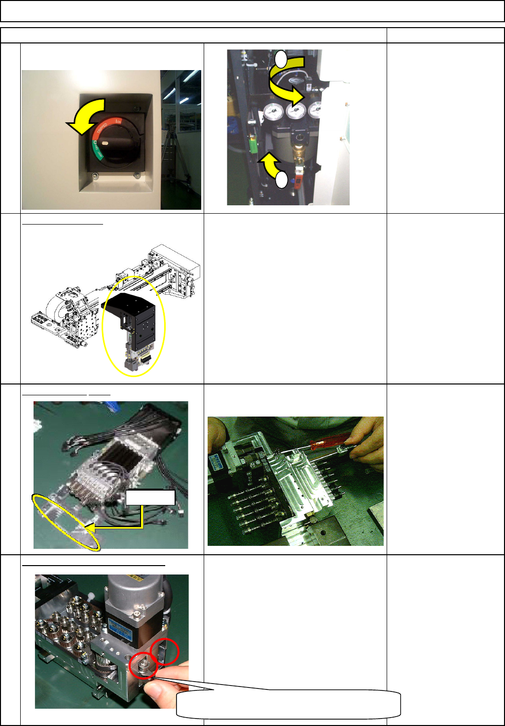
Machinery Part Replacement Remark Turn off the power and air supply. 0.49MPa to 0.55MPa Remove the head. 1-000279 See "12-Nozzle-Head-Unit Replacement." Section 5-10-1 Se p arate the θ -unit. See " θ -Unit…
Machinery Part Replacement
This section describes the procedures for replacing the θ-axis motor.
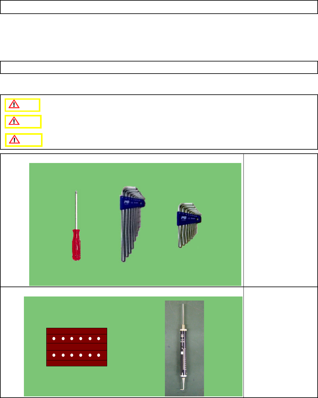
Tools
Phillips screwdriver #1
Allen key
Jig
θ
-control jig
Tension gauge
5-10-6 θ-axis Motor Replacement
12-Nozzle Head Unit
Caution
Dange
r
Warning
EJM8A-E-SMA051006-A01-00
Page 5-10-6-1
Machinery Part Replacement
Remark
Turn off the power and air supply.
0.49MPa to
0.55MPa
Remove the head.
1-000279
See "12-Nozzle-Head-Unit
Replacement."
Section 5-10-1
Se
p
arate the
θ
-unit.
See "θ-Unit Removal."
Section 5-10-8
Remove the short belt tensioner.
1-000314
Allen key 3 mm
M3 x 12L 2 pcs.
12-Nozzle Head Unit
Item
2
3
4
1
1
2
The adjuster-holding bolt is under the adjuster.
One bolt for each adjuster
Dowel pin
EJM8A-E-SMA051006-A01-00
Page 5-10-6-2
Machinery Part Replacement
Remark
12-Nozzle Head Unit
Item
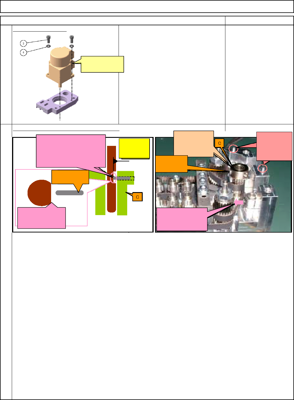
Re
p
lace the θ-motor.
Allen key 3 mm
M4 x 12L 2 pcs.
Mount the
p
late
(
B
)
on the θ-axis housin
g
.
6
5
The connector is on
this side.
Pressing the end of the
hollowset against the D-
shaped cut, fix the shaft and
the pulley (C) in place.
The D-shaped cut
should face the
hollowset.
ホロセット
:C組み付け
済
D-shaped cut
of the motor
shaft
Should NOT be
raised when
fixed.
Insert these
dowel pins into
the holes of the
plate (B).
Press D against the
timing belt and adjust
the tension.
Hollowset:
coupled with C
Hollowset:
coupled with C
1. Mount the plate (B) on the θ-axis housing (A).
Make the D-shaped cut of the motor shaft face the hollowset (coupled with the pulley C).
Insert the dowel pins (coupled with A) into the holes of B.
2. Fix the pulley (C) and the motor shaft with the hollowset (coupled with C).
Fix the hollowset onto the D-shaped cut of the motor shaft. Press down C to avoid letting C rise.
3. Centering of the motor
If the pulley (C) does not rotate smoothly, center the motor. (Ex. Loosen the bolts that fix the motor
onto the plate (B).)
4. Fit the tension adjuster C (D) onto the θ-axis housing (A) with (3) and (4).
Pressing D against the timing belt, fix it onto A with (3) and (4).
5. Fit the tension adjuster B (E) onto the θ-axis housing (A) with (3) and (4).
Pressing E against the timing belt, fix it onto A with (3) and (4).
6. Adjust the tension of the timing belts by controlling the tension adjusters (D, E, and F).
Great care must be taken for the surrounding of each pulley when adjusting the tension.
EJM8A-E-SMA051006-A01-00
Page 5-10-6-3