CM602all_EJM8AESM_Service Manual.pdf - 第645页
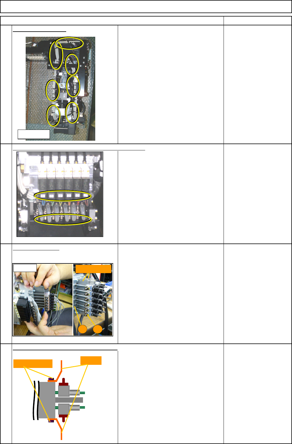
Machinery Part Replacement Remark 12-Nozzle Head Unit Item Remove the air-valve unit. Loosen the four M3 x 16L bolts, and remove them. Allen key M3 x 16L Four of each Remove the vacuum sensor. Repeat this step for the re…
Machinery Part Replacement
Remark
12-Nozzle Head Unit
Item
Cut off the cable ties.
Nipper
Remove the vacuum hose and the valve connectors.
Repeat this step for the rear side.
Insert the plate jig.
Insert the plate jig between the spline
housing (A) and the θ-axis unit (B).
Repeat this step for the rear side.
Plate jig
Remove the vacuum-valve-cable bracket.
Repeat this step for the rear side.
CBSS3-6 4 pcs.
5
7
6
4
<Left side>
<Fig. 1>
Plate jig
A
B
Bracket
Bolt (CBSS3-6)
EJM8A-E-SMA051007-A01-00
Page 5-10-7-3
Machinery Part Replacement
Remark
12-Nozzle Head Unit
Item
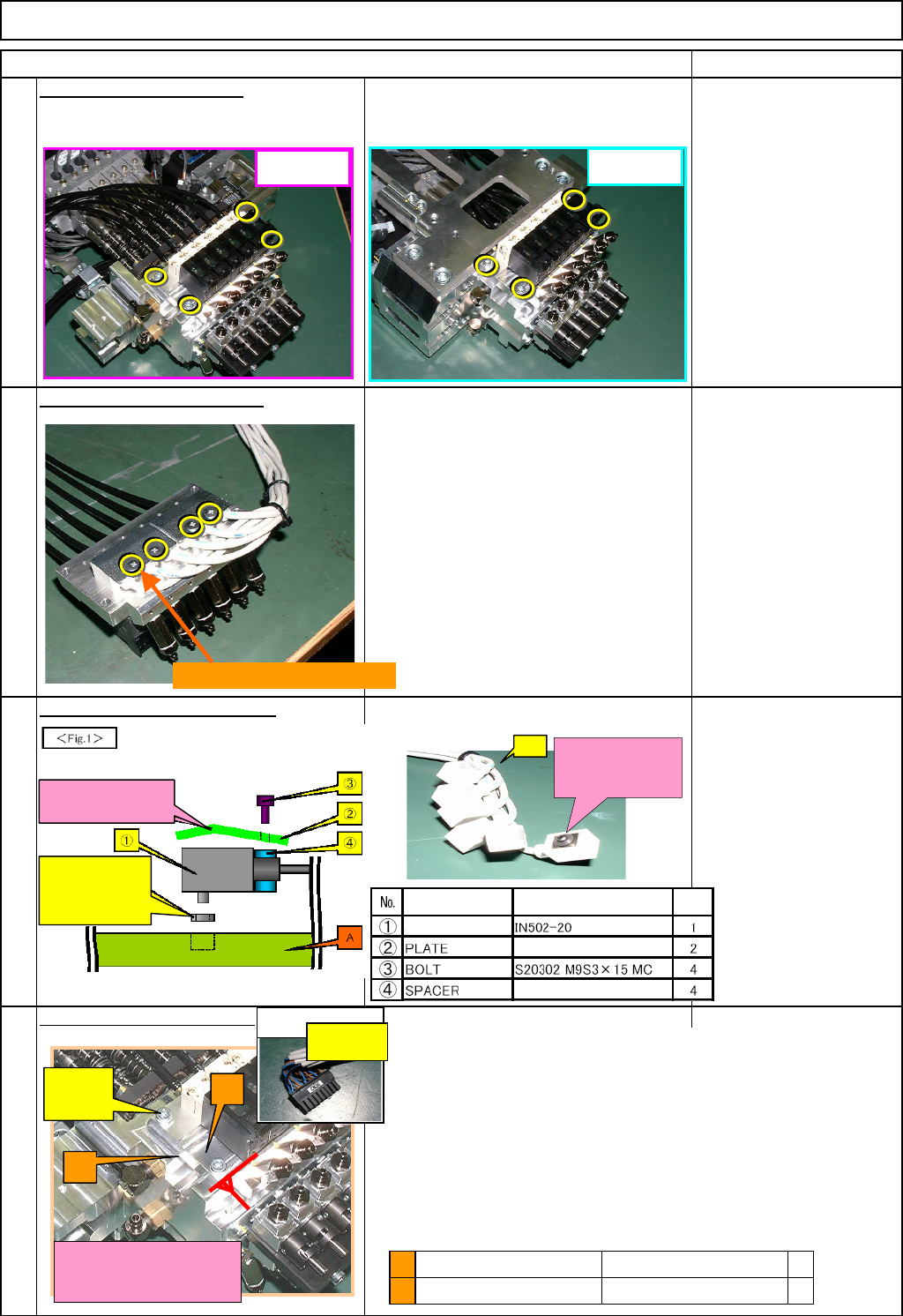
Remove the air-valve unit.
Loosen the four M3 x 16L bolts, and
remove them.
Allen key
M3 x 16L Four of each
Remove the vacuum sensor.
Repeat this step for the rear side.
Phillips screwdriver
S20302 M9S3×15MC
Assemble the vacuum sensor.
Repeat this step for the rear side.
Phillips screwdriver
S20302 M9S3×15MC
Assemble the air-valve unit.
8
9
10
11
FWD
REAR
S20302 M9S3×15MC (4 pcs)
(1)
Coupled with O-
shaped ring
A
C
(1) & (2)
(A) should make a close contact
with C and the red line above.
Same to rear side.
Check the direction
in which it is bent.
(1) Accessory of
O-shaped ring
Part name Model
Qty
SENSOR
(
NP7-12
)
1. Check the air-valve units (A) and (B) beforehand.
Identify (A) and (B) with the vacuum connectors, and check
that each cable is connected to the correct position.
2. Fit the air-valve units (A) and (B) onto the main body of the
head (C) with (1) and (2) at the specified torque.
Tightening torque: 157N•cm
(A) should make a close contact with (C) when fixing (A).
Be careful there is no foreign matter.
3. Put the tube between the main body of the head (C) and the
plate (D).
Be careful not to break the tube.
B
A
Air-valve unit (Rear)
Air-valve unit (Front)
* NP7 to 12 (A002)
* NP1 to 6 (A001)
1
1
A & B identified with
connector
FWD: CN36
(REAR: CN35)
EJM8A-E-SMA051007-A01-00
Page 5-10-7-4
Machinery Part Replacement
Remark
12-Nozzle Head Unit
Item
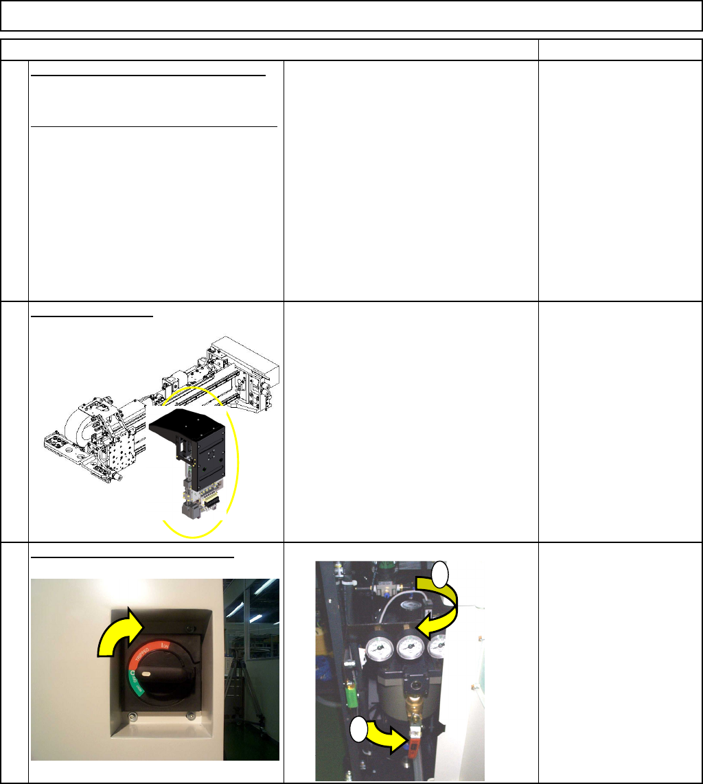
Assemble the unit in the reverse order.
Repeat Steps 3 to 7 in the reverse order.
Install the head unit.
See "12-Nozzle-Head-Unit
Replacement."
Section 5-10-1
Turn on the power and air supply.
13
12
14
1
2
EJM8A-E-SMA051007-A01-00
Page 5-10-7-5