CM602all_EJM8AESM_Service Manual.pdf - 第664页
Machinery Part Replacement Remark 12-Nozzle Head Unit Item Replace the arm. Be careful not to position the arm upside down. Fit the spring and the nozzle holder 5 4 Narrow Wide EJM8A-E-SMA051010-A01-00 Page 5-10-10-3
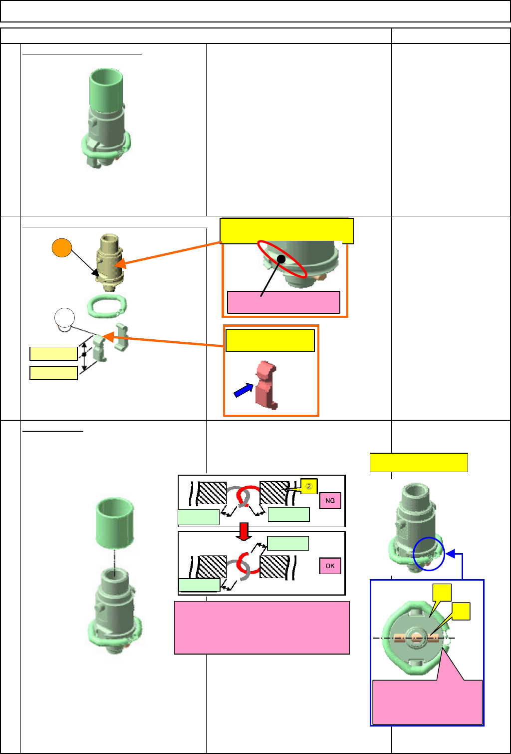
Machinery Part Replacement
Remark
Remove the nozzle holder.
Remove the spring and apply grease to it.
Barrierta IEL
Fit the spring.
12-Nozzle Head Unit
3
1
Item
2
A
1
A: Grease position
(Same to opposite side)
* Groove with which the
clam
p
arm makes contact.
Ref. Finished image
One side of c and the
hook of the d should be
positioned on the same
side.
d
c
Narrow
Wide
Open side
Open side
Open side
Open side
Position the hooks so that the two
"open sides" should not face in the
same direction when the spring is fit.
cGrease position
EJM8A-E-SMA051010-A01-00
Page 5-10-10-2
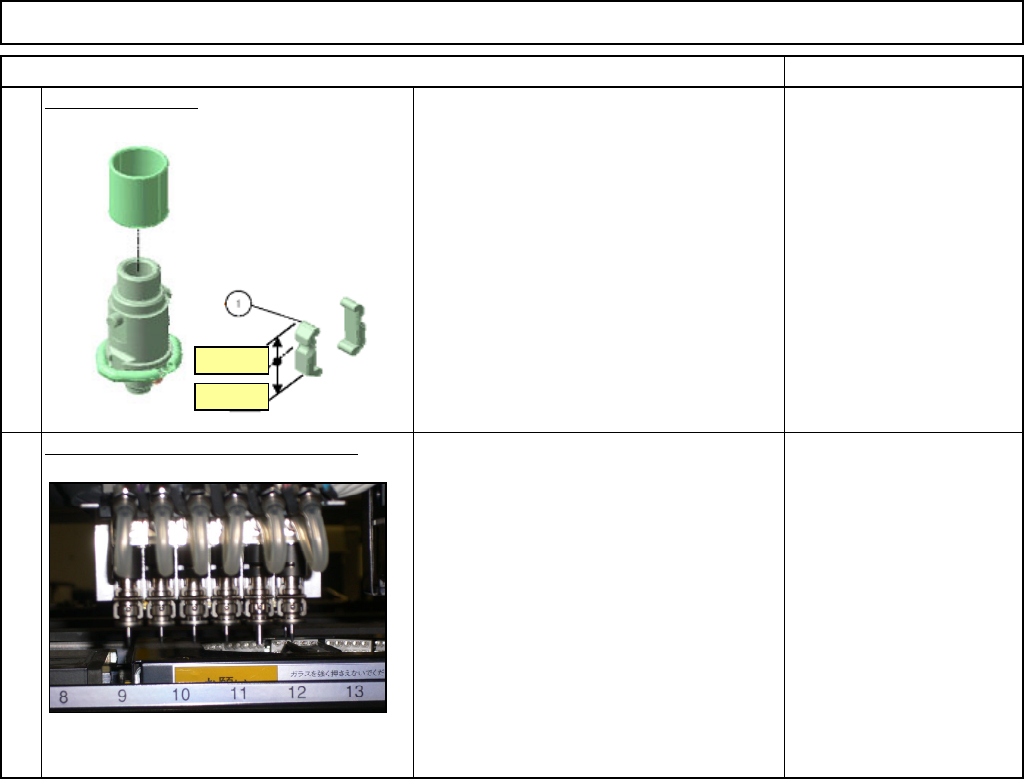
Machinery Part Replacement
Remark
12-Nozzle Head Unit
Item
Replace the arm.
Be careful not to position the arm upside
down.
Fit the spring and the nozzle holder
5
4
Narrow
Wide
EJM8A-E-SMA051010-A01-00
Page 5-10-10-3
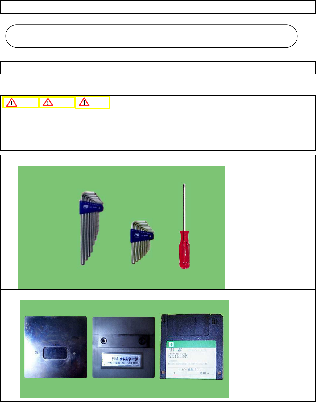
Machinery Part Replacement
This section describes the procedures for focusing the head camera and positioning it in the theta direction.
・Tools
Phillips screwdriver #2
Allen key 1.5 mm
Allen key 3.0 mm
・Jig
Head camera focusing jig
Key disk
5-11-1 Head Camera Adjustment --- Focus and θ
1. Since this adjustment requires parameter changes using the key disk, only those who are authorized to use
the key disk based on the Document "Key Switch/Key Disk Receipt Confirmation and Safety Precautions" are
permitted to perform this adjustment.
2. Remove the support pins beforehand.
12-Nozzle Head Teaching
Caution
Dange
r
Warning
12-Nozzle Head Teachin
g
5-11
EJM8A-E-SMA051101-A01-00
Page 5-11-1-1