CM602all_EJM8AESM_Service Manual.pdf - 第670页
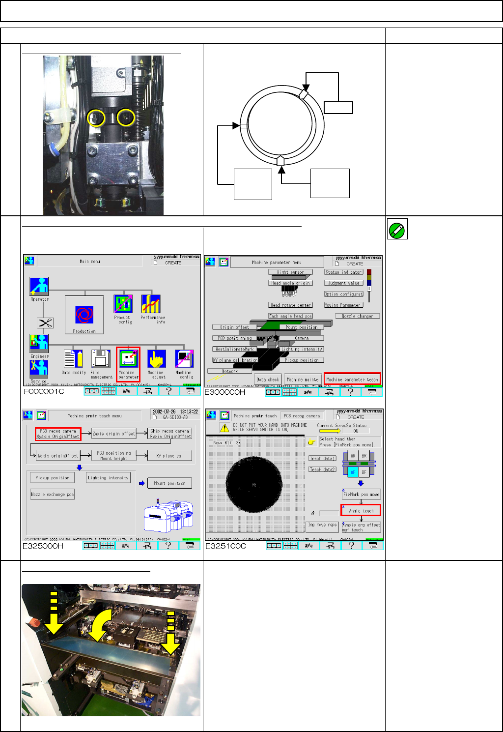
Machinery Part Replacement ・ Tools None ・ Jig None 12-Nozzle Head Teaching 5-11-2 Board Recognition Camera --- X and Y-axis Origin Offset Clean the upper surface of the thermal correction pole beforehand. This section de…
Machinery Part Replacement
Remarks
Item
12-Nozzle Head Teaching
Tighten the theta holding set screws.
Allen key 1.5 mm
Teach "Board Recognition Camera - X and Y-axis Origin Offset."
For details, see Sections at right. Section 5-11-2
Specifications:
within +/- 0.05°
Put the feeder cover back on.
Phillips screwdriver #2
Screw M4 2 pcs.
15
14
13
Lightly
tighten
Lock
No
screw
ON
EJM8A-E-SMA051101-A01-00
Page 5-11-1-5
Machinery Part Replacement
・Tools
None
・Jig
None
12-Nozzle Head Teaching
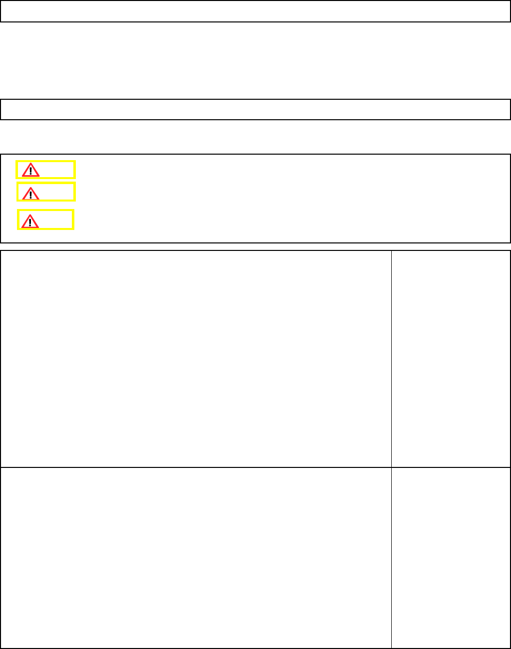
5-11-2 Board Recognition Camera --- X and Y-axis Origin Offset
Clean the upper surface of the thermal correction pole beforehand.
This section describes the procedures for setting the offset for the origin of the X- and the Y-axes of the board
recognition camera.
Caution
Dange
r
Warning
EJM8A-E-SMA051102-A01-00
Page 5-11-2-1
Machinery Part Replacement
Remarks
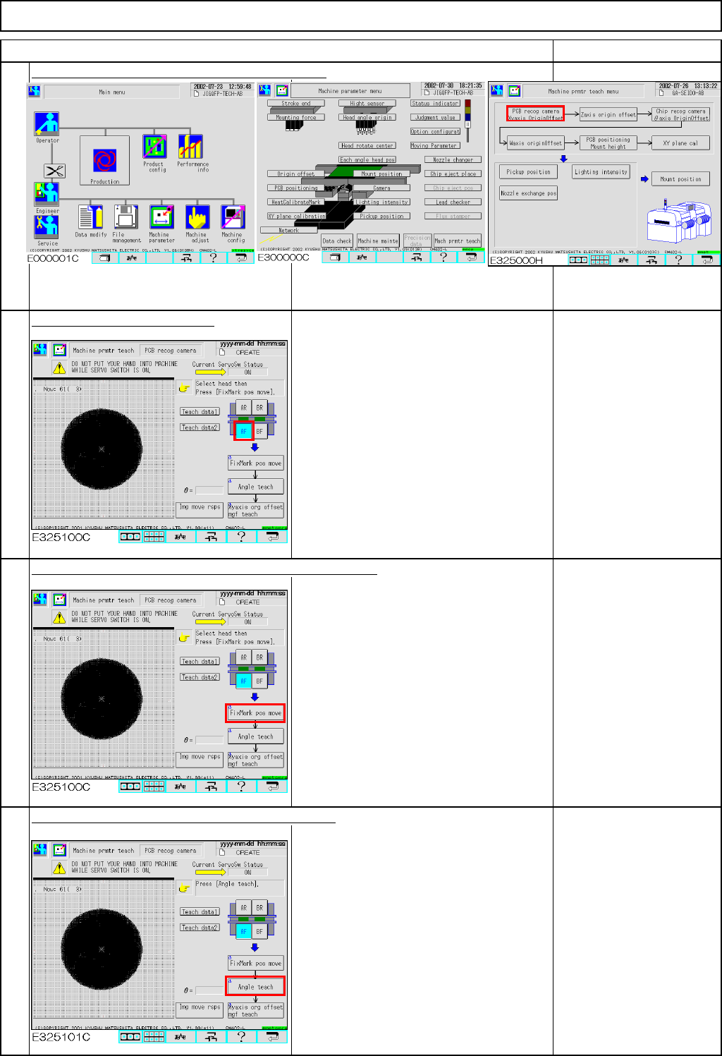
Press [PCB recog camera Xyaxis OriginOffset].
Select the stage to be taught.
Press [Unlock] and [FixMark pos move] simultaneously.
The head camera for the selected stage
moves to the heat calibration mark.
The head camera recognizes the mark.
The offsets for the X- and the Y-axes are
entered.
If the mark is not
displayed on the window,
adjustment with the XY-
axis origin jig failed.
Press [Unlock] and [Angle teach] simultaneously.
The head camera recognizes the mark.
The offset for the angle of the camera is
entered.
"Angle teach" error:
If the theta is out of the
range of +/- 0.2°,
this error will occur.
See Section 5-11-1
"Head Camera
Adjustment - Focus and
Theta."
1
Item
12-Nozzle Head Teaching
2
3
4
EJM8A-E-SMA051102-A01-00
Page 5-11-2-2