CM602all_EJM8AESM_Service Manual.pdf - 第68页
Lower the Adjusting Bolts B and E to the floor so that the feet of the bolts do not move. Rotate the bolts 45 degrees and lock the lock nuts. Once adjustment has been complete, lock the adjusting bolts. Put a mark on the…
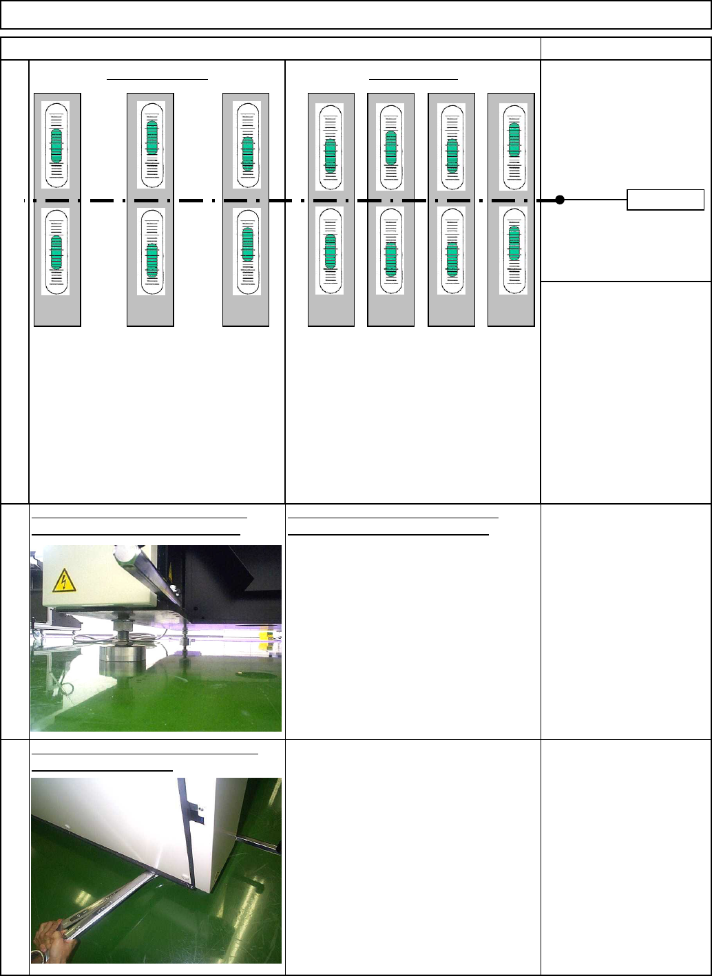
The levels at left shows
the relationshi
p
between
(
1
)
and
(
3
)
or
(
2
)
and
(
4
)
above:
the range of 900 to 920 mm.
Leave the center adjusting bolt raised.
Tools and Specification
lock the adjusting bolts.
Wrench 45 mm 2 pcs.
When the reading s of levels (1) and (3),
and (2) and (4) are matched with one of
the examples A, B and C, the machine is
leveled.
[Specifications]
The levels of each position should be
symmetrical. Difference should be 0.04
mm/m or less. (1 div. should be 0/02
mm/m)
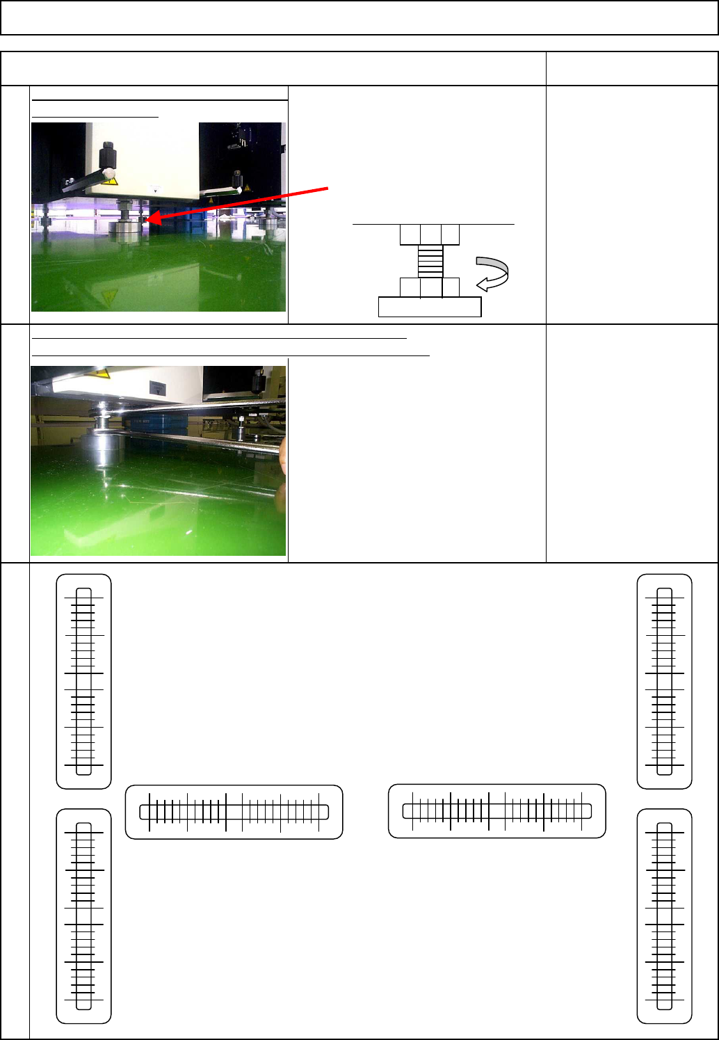
When the readings of levels (1) and (3), and
(2) and (4) are not symmetrical as shown in
the examples D, E, and F, the machine is not
leveled correctly.
Even when the bubble of one of the levels is
positioned in the center, the levelness is not
acceptable.
[Specifications]
The levels of each position should be
symmetrical. Difference should be 0.04 mm/m
or less. (1 div. should be 0.02 mm/m)
4-7)
Levelness: Good Levelness: NG
5
Adjust Adjusting Bolts A, C, D and F
Checking the height of the transfer
Tools and Specification
checking Levels 1, 2, 3, 4, 5 and 6.
conveyor belt, adjust the height to
Level
Wrench 45 mm
Spec.: 0.04 mm or less
6
Once adjustment has been complete,
Item
Setting Machine Setting
Remarks
A GB C D E F
Center line
EJM8A-E-SMA020102-A01-00
Page 2-1-2-5
Lower the Adjusting Bolts B and E to the
floor so that the feet of the bolts do not
move. Rotate the bolts 45 degrees and
lock the lock nuts.
Once adjustment has been complete, lock the adjusting bolts.
Put a mark on the lock nut. Check that the bolt is seated securely.
7
Lower the center adjusting bolt to the floor
Tools and Specification
Check the levelness.
Level
Wrench 45 mm
Spec.: 0.04 mm or less
45°
9
8
Wrench 45 mm 2 pcs.
Setting Machine Setting
Item Remarks
(1)
(3)
(2)
(4)
(5)
(6)
EJM8A-E-SMA020102-A01-00
Page 2-1-2-6
Caution 1. Be sure to turn off the servo switch before working on the machine.
Caution 2. When inspection is carried out by two or more persons, give appropriate
warning to each other.
Caution 3. Watch your head while working on the machine.
Caution 4. After finishing the inspection of the delivery installation procedures, carry out
delivery inspection.
Caution 5. Slowly move up and down the voltage adjustment volume of the DC electric
source. Suddenly moving it up may break the board.
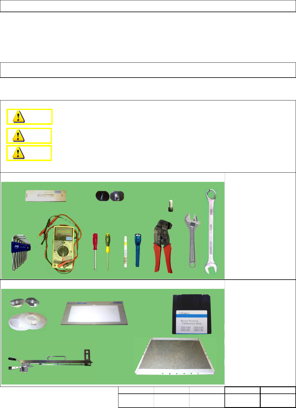
・Level
・Nozzle
・Allen key
・Sleeve
・Phillips screwdriver
・Flat-head screwdriver
・Adjustable wrench
・Combination wrench
・Pen light
・Magic marker
・Clamper
Tester
・Nozzle changer jig
・1005 and 0603 R components
・Pickup position teaching jig
・Placement correcting
position teaching jig.
・Placement correcting
position teaching data (FD)
・Nozzle 110 24 pcs.
・ Tape Feeder 0.5P 4 pcs.
min.
・This section describes the procedures for inspecting the equipment when it is delivered.
・Tools
・Jigs
min.
kgs
0
Installation Machine Installation
2-1-3 Delivery Inspection
Part weight
Teaching
Assembly/AdjustmentRemoval/Disassembly
min.min.
Danger
Warning
Caution
EJM8A-E-SMA020103-A01-00 Page 2-1-3-1