CM602all_EJM8AESM_Service Manual.pdf - 第703页
should be positioned on the reference side. Prepare the stage to teach as shown below. • Turn on the power switch of the light box. (Do not connect the plug yet.) • The narrow side between the end and the lighting portio…
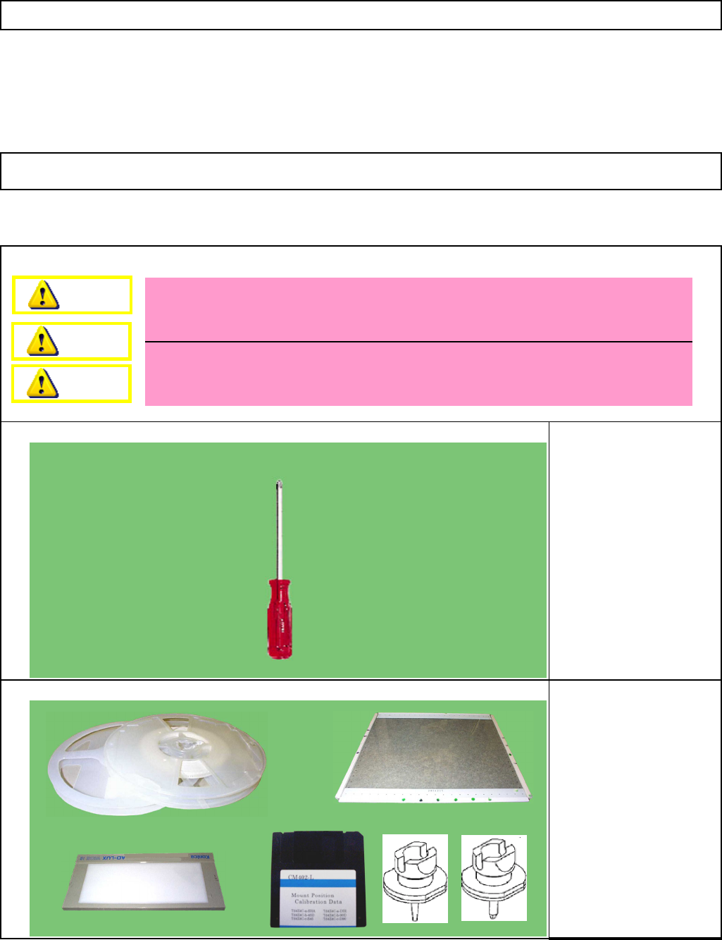
Tool
Jig
5-11-11
Mounting Position
This section describes the procedures for teaching the mounting position.
* When the machine is warmed up for some reason such as a test run, cool down the
machine by powering down the machine and opening the four upper covers before
teaching.
* When teaching the machine that has been left powered down for some time, carry out
a one-cycle test run using the "Mount position teaching - Warmup operation."
Mounting position
correcting data
Light Box
Glass board
(240x215 TH: 2.4)
Component 1005R 2 pcs.
Component 0603R 2pcs.
Nozzle 110S 48 pcs.
Nozzle 205S 48 pcs.
Double-sided tape
Machinery Part Replacement 12-Nozzle Head Teaching
Phillips screwdriver #2
Dange
r
Warning
Caution
EJM8A-E-SMA051111-A01-00
Page 5-11-11-1
should be positioned on the reference side.
Prepare the stage to teach as shown below.
• Turn on the power switch of the light box. (Do not connect the plug yet.)
• The narrow side between the end and the lighting portion of the box
RemarksItem
1
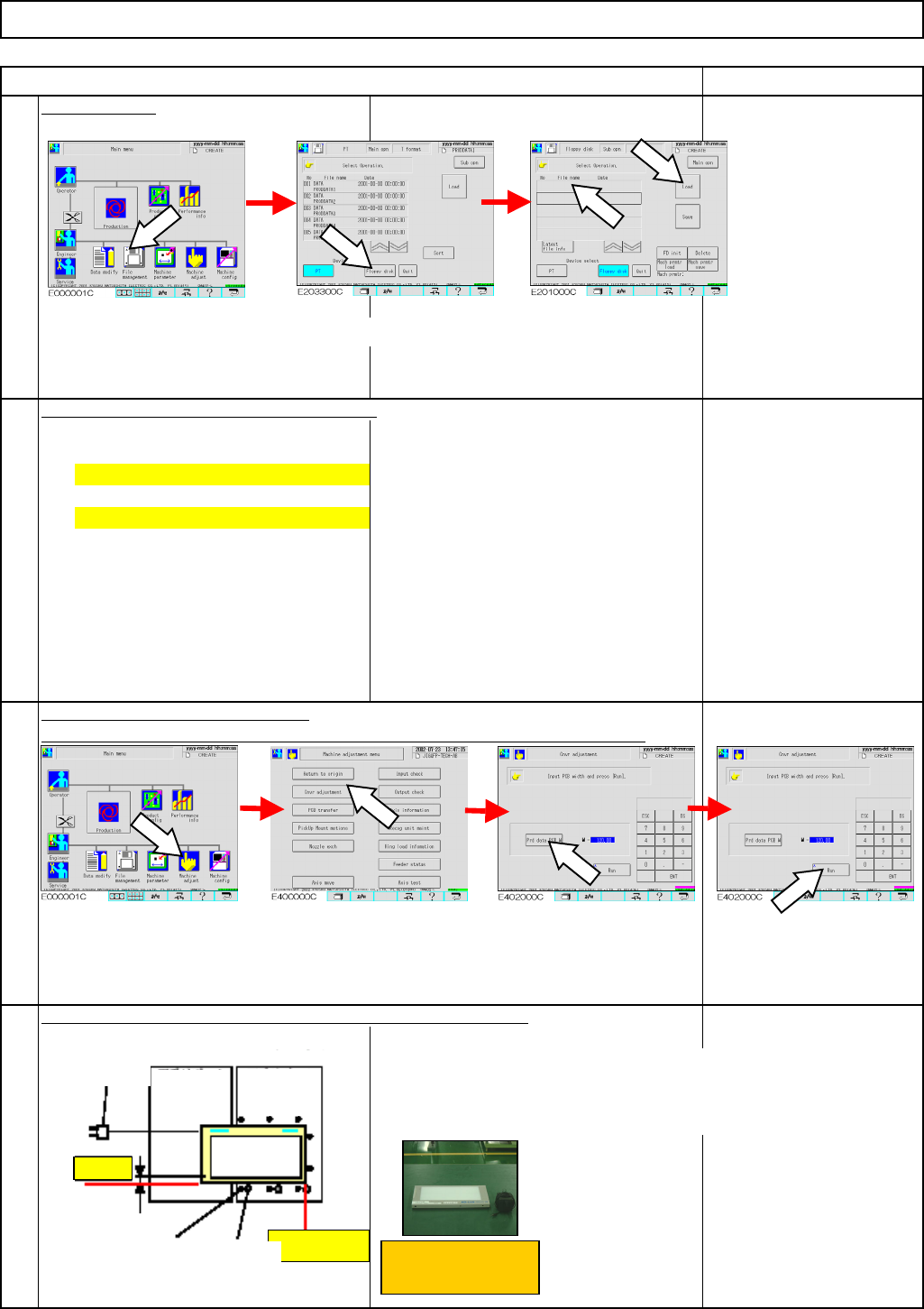
Load the data.
Direct recognition: [TdEJM4A-a2-DIR0]
Adjust the width of the conveyors.
Shadow recognition: [TdEJM4A-a2-SHA0]
Put the pins on the pin plate. Put the light box in the machine.
Select the teaching data and press [Load].
* To avoid pin interference, check there are no pins on the plate beforehand.
2
3
4
Machinery Part Replacement 12-Nozzle Head Teaching
Light box
Press [File management].
Press [Floppy disk].
Press [Machine adjust]. Press [Cnvr adjustment]. Press [Prd data PCB w].
Press [Run].
Plug
Support
block
(
Left
)
Support
block (Right)
Light box
Ref.
id
Stopper side
Narrow side
Pin position
Truss screw
EJM8A-E-SMA051111-A01-00
Page 5-11-11-2
Conveyor ref. side ...
Board stopper side ...
Movable conveyor ...
side
• Put one sheet of paper (plain paper) on the light box.
(To reduce light intensity)
• Put the light box on the stage to teach.
• Shadow recognition teaching: 110S
• Direct recognition teaching: 205S
• Shadow recognition teaching: Feeder change cart
Work: 1005R
Work-setting position: Left of the tape feeder
• Direct recognition teaching:
Work: 0603R
Work-settin
g
position: Ri
g
ht of the tape feeder
Tape feeder
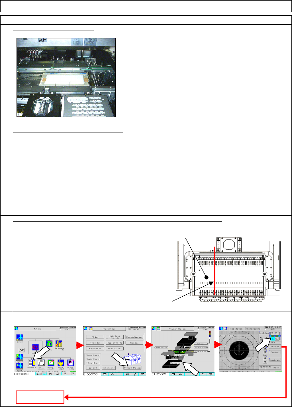
Press [Production data teach].
Press [Pick pos learning].
Select the stage.
Remarks
5
Put the light box in the machine.
to the stopper. (Same pitch: Visual check)
Three pins: Press the light box against the above-
Machinery Part Replacement 12-Nozzle Head Teaching
• Put pins on the following positions, and put the light box in the machine.
mentioned pins and position pins along the box.
Three pins: One for next to each truss screw
(Opposite side of each truss screw to the stopper.)
Two pins: Vertical side of the plate corner close
Put an 8-mm-wide tape feeder on the number 7 position of each feeder change cart
.
(12 nozzles for each head, 48 for all stages)
7
8
Adjust the pickup position.
Press [Data modify].
6
Item
Fit the nozzles on all the nozzle holders for a head.
To Step 9
EJM8A-E-SMA051111-A01-00
Page 5-11-11-3