CM602all_EJM8AESM_Service Manual.pdf - 第767页
18 16 Set up the DIP switches, which are Allen key 3 mm Screw M4 2 pcs. located at the rear side of the amplifier. Fit Bracket ⑥ . Fix the amplifier in place. Insert the amplifier. Phillips screwdriver #2 Terminal screw …
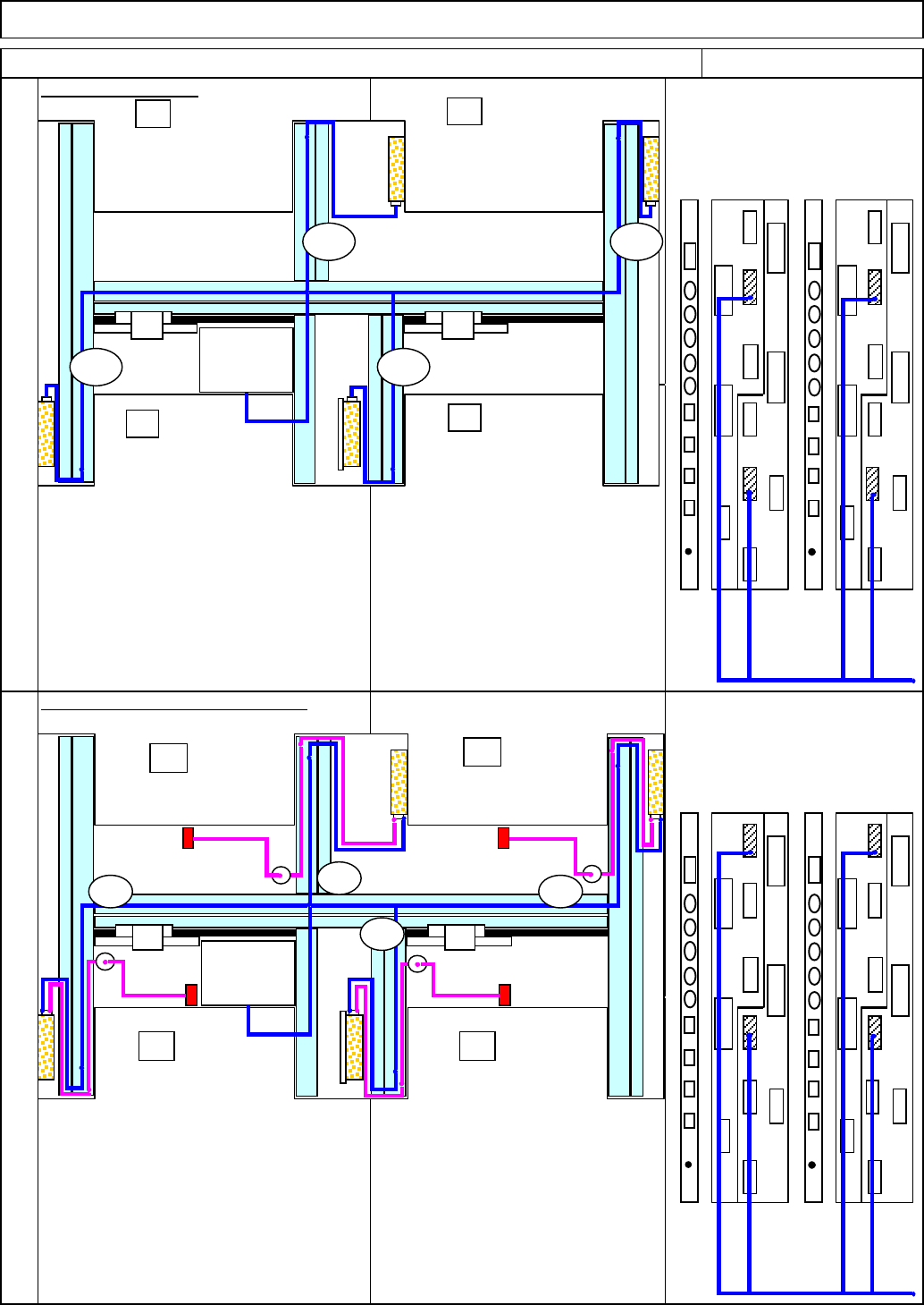
C-1: CN5 to INTENS,DISPLACE
(LB1 to LZ1)
C-2: CN5 to INTENS,DISPLACE
(LB2 to LZ2)
C-3: CN5 to INTENS,DISPLACE
(LB3 to LZ3)
C-4: CN5 to INTENS,DISPLACE
(LB4 to LZ4)
D-1:CN4-LB1 to ANALOG-LZ1
The section of a cable connected
D-2:CN4-LB2 to ANALOG-LZ2 from 〇 to the sensor is
p
ositione
d
D-3:CN4-LB3 to ANALOG-LZ3
on the upper surface of the body
D-4:CN4-LB4 to ANALOG-LZ4
frame.
Remark
Optional Accessory Parts Replacement Lead Checker
Item
Laser Analog Signal Cable Layout
15
14
Signal Cable Layout
CN10
SW1
CN5
CN1 CN2
CN3
CN4 CN6
CN7 CN8
CN9
CN10
SW1
CN5
CN1
CN2 CN3 CN4 CN6 CN7 CN8 CN9
CN7-P CN7-P
CN4-P CN4-P
CN5-P
CN5-P
CN2
CN2 CN3
CN3
CN1
CN1
CN7-P CN7-PCN4-P CN4-P
CN5-P
CN5-P
CN2
CN2
CN3
CN3
CN1
CN1
LB1
LB2
LB3
LB4
AF
A4A4
POWER
UNIT#1
POWER
UNIT#2
CPUBOX
AR
BF
BR
C-2 C-4
C-3C-1
INTENS
DISPLACE
LZ1
INTENS
DISPLACE
LZ4
INTENS
DISPLACE
LZ3
INTENS
DISPLACE
LZ2
CN10
SW1
CN5
CN1 CN2
CN3
CN4 CN6
CN7 CN8
CN9
CN10
SW1 CN5CN1 CN2 CN3 CN4 CN6CN7 CN8 CN9
CN7-P CN7-P
CN4-P
CN4-P
CN5-P
CN5-P
CN2
CN2 CN3
CN3
CN1
CN1
CN7-P CN7-P
CN4-P
CN4-P
CN5-P
CN5-P
CN2
CN2
CN3
CN3
CN1
CN1
LB1
LB2
LB3
LB4
AF
A4A4
POWER
UNIT#1
POWER
UNIT#2
CPUBOX
AR
BF
BR
D-2
D-4
D-3
D-1
ANALOG
LZ1
ANALOG
LZ4
ANALOG
LZ3
ANALOG
LZ2
Sensor
Sensor
Sensor
Sensor
EJM8A-E-SMA060301-A01-00
Page 6-3-1-7
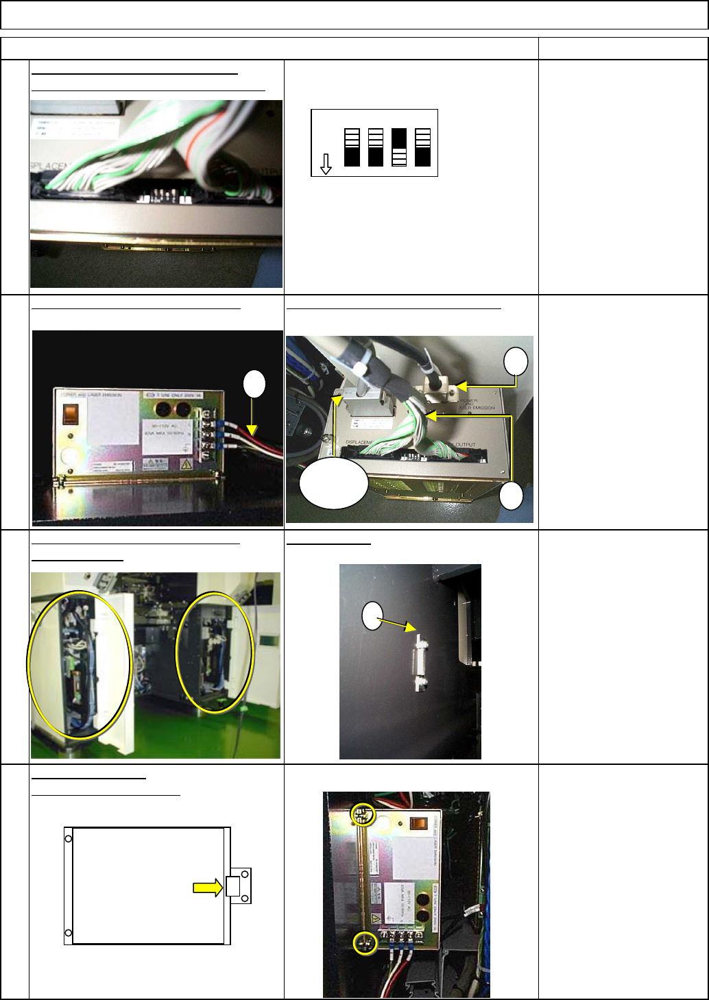
18
16
Set up the DIP switches, which are
Allen key 3 mm
Screw M4 2 pcs.
located at the rear side of the amplifier.
Fit Bracket ⑥.
Fix the amplifier in place.
Insert the amplifier.
Phillips screwdriver #2
Terminal screw 3 pcs.
17
Optional Accessory Parts Replacement Lead Checker
Item Remark
Connect the amplifier power cable.
Connect the communication cables.
Open the left covers on the AF, AR
Amplifier holding bracket
(small)
Allen key 3 mm
Screw M4 2 pcs.
19
and BR stages.
C
D
Sensor
cable
A
12 3 4
ON
6
EJM8A-E-SMA060301-A01-00
Page 6-3-1-8
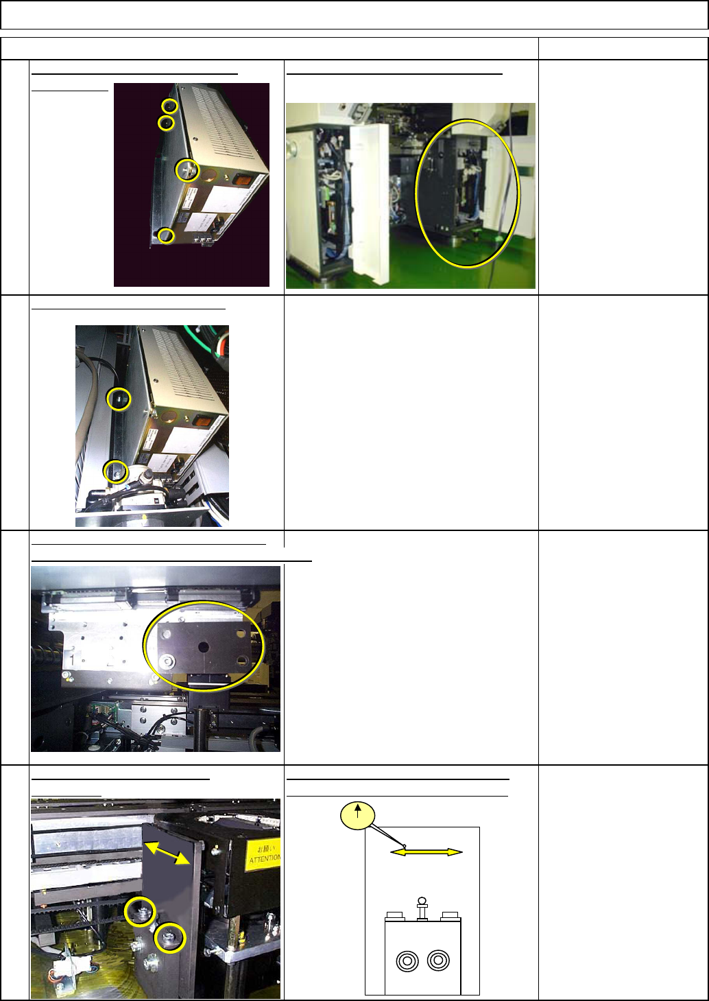
Optional Accessory Parts Replacement Lead Checker
21
Install the amplifier in the center.
Item Remark
20
Put Bracket (5) on the rear side of
Amplifier (7).
Allen key 3 mm
Screw M4 4 pcs.
Allen key 3 mm
Screw M4 1 pc.
Iron plate for holding the
magnetic stand
Place the iron plate on the head so that
the magnetic stand can be placed on the plate.
Bracket (3).
Specifications:
Parallelism:
0.02 mm or less
Allen key 3 mm
Allen key 4 mm
Screw M4 2 pcs.
Screw M5 2 pcs.
Magnetic stand
Dial gauge
Adjust the bracket so that it is parallel
to the Y-axis. Fix the bracket in place.
23
Lightly tighten Sensor Holding
22
Open the left cover on the BF stage.
Allen key 3 mm
Screw M4 2 pcs.
EJM8A-E-SMA060301-A01-00
Page 6-3-1-9