CM602all_EJM8AESM_Service Manual.pdf - 第784页
Remark Item Component-Thickness-Measuring Unit Option Part and Accessory Replacement Check the value of the amplifier. Pre p are the holdin g bolts. Fit the am p lifier-holdin g bolt. ( 1 ) Phillips screwdriver #2 Screw …
Remark
Item
Component-Thickness-Measuring Unit
Option Part and Accessory Replacement
Chan
g
e the am
p
lifier out
p
ut t
yp
e to "1."
Settin
g
of nozzle rear line
(
7 to 12
)
CN39
36
35
34
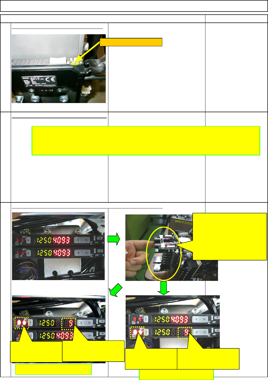
Check the condition of the amplifier with the sensor light blocked.
Repeat the above-mentioned procedures
to set the other amplifier.
After finishing setting the
amplifier, blocking the light
of the front (1 to 6) and the
rear sensors (7 to 12) one by
one, check the condition of the
amplifier for the front and rear
separately.
Rear sensor (7 to 12)
Front sensor (1 to 6)
With the sensor light
blocked, this light
should be turned ON.
With the sensor light
blocked, the value should
be reduced.
With the sensor light
blocked, this light
should be turned ON.
With the sensor light
blocked, the value should
be reduced.
Switch the channel to "1."
EJM8A-E-SMA060401-A01-01
Page 6-4-1-11
Remark
Item
Component-Thickness-Measuring Unit
Option Part and Accessory Replacement
Check the value of the amplifier.
Pre
p
are the holdin
g
bolts.
Fit the am
p
lifier-holdin
g
bolt.
(
1
)
Phillips screwdriver #2
Screw M4
37
38
39
40
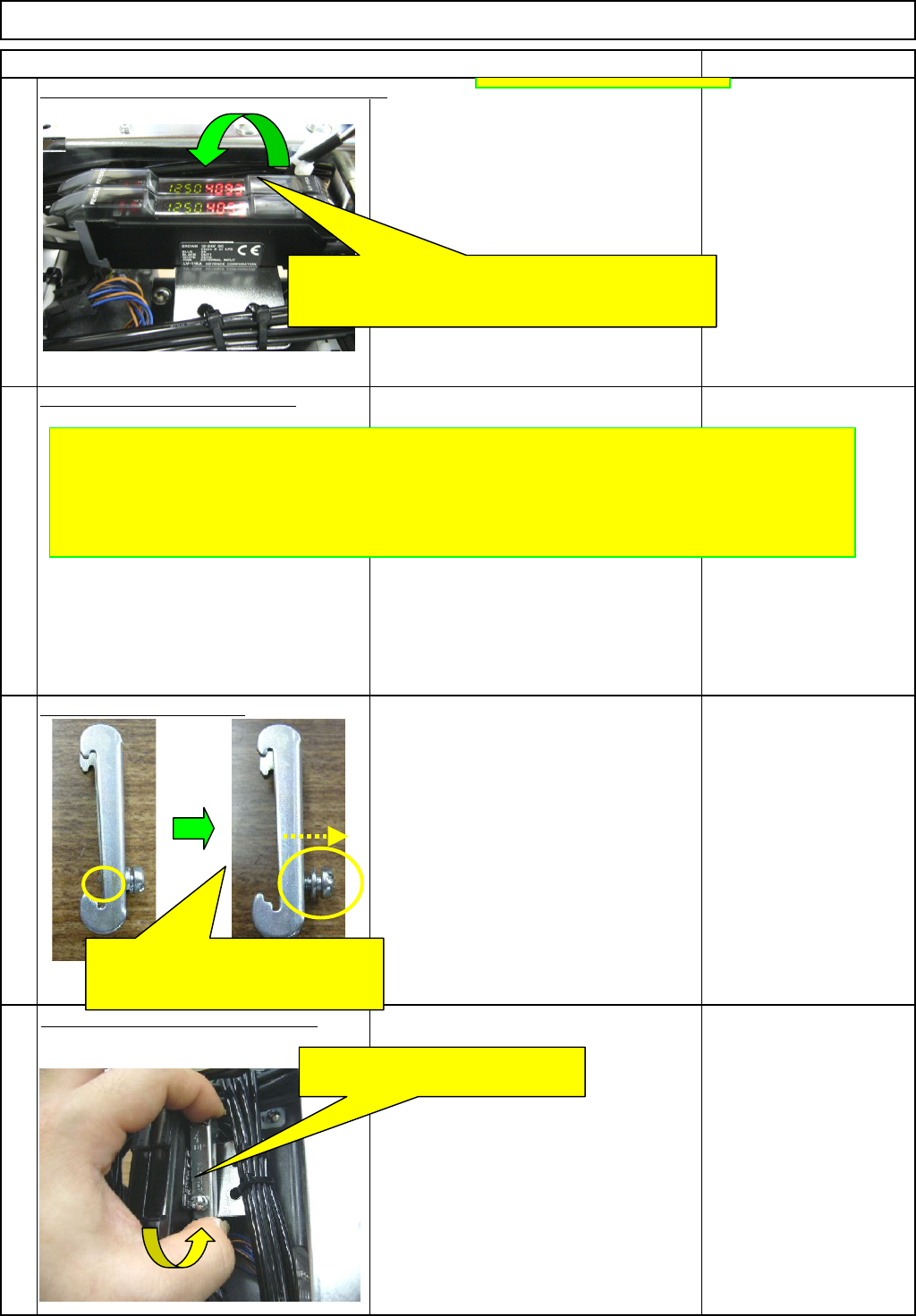
Close the amplifier cover, and finish setting.
()
When everything is all right, close the amplifier cover
and finish setting.
* If no good is found, review the amplifier setting.
Block the light with the filter, and check each value (front and rear)
of the amplifier is 600 or more.
* If a value is less than 600, re-adjust the sensor until the
value is 600 or more.
Loosen the holding bolt until the end
of it does not come out to the
rear side of the bracket.
Press the bolt end of the bracket
against the cables to lock that end.
EJM8A-E-SMA060401-A01-01
Page 6-4-1-12
Remark
Item
Component-Thickness-Measuring Unit
Option Part and Accessory Replacement
Fit the am
p
lifier-holdin
g
bolt.
(
2
)
Fit the am
p
lifier-holdin
g
bolt.
(
3
)
Phillips screwdriver #2
Screw M4
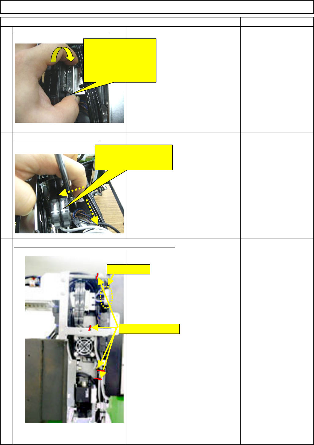
Insert the CNs39 and 40. Secure the cables with cable ties.
41
42
43
Press the other end of
the bracket against the
cables to lock that end.
Move the bracket in
the ↓ direction.
Pressing the bracket in the
↓ direction and against the
amplifier, tighten the bolt.
Securing cable ties
CN39 and 40
EJM8A-E-SMA060401-A01-01
Page 6-4-1-13