CM602all_EJM8AESM_Service Manual.pdf - 第834页
Remark Component-Thickness-Measuring Unit Item Option Part and Accessory Replacement Install the sensor. 1.Insert the plate (D) into the sensor (C) that has the M6 nut (1). Screw the slit (A) fully. Unscrew the slit slig…
Remark
Component-Thickness-Measuring Unit
Item
Option Part and Accessory Replacement
<Caution>
One bushing (See the picture at right.) is
under each Hexagon-socket-head
setscrew. Be careful not to lose the
bushing.
Wrench M3
Hexagon-socket-head
setscrew M3 x 4L
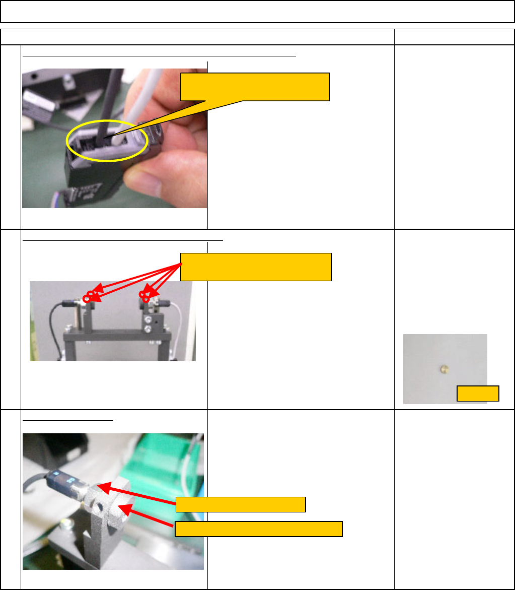
Remove the sensor.
(1) Holding the slit with an M12 wrench,
loosen the M6 nut with an M10 wrench.
(2) Turn the slit to the left. Remove it
from the sensor. Remove the sensor.
Wrench M10
Wrench M12
Nut M6
11
9
10
Remove the sensor cables from the amplifier connector lock.
Loosen the Hexagon-socket-head setscrews.
Remove the sensor cables from
the amplifier connector lock.
Hexagon-socket-head setscrews
M3 x 4L (2 for each)
Hold it with an M12 wrench.
Loosen the nut with an M10 wrench.
Bushing
EJM8A-E-SMA060405-A01-00
Page 6-4-5-4
Remark
Component-Thickness-Measuring Unit
Item
Option Part and Accessory Replacement
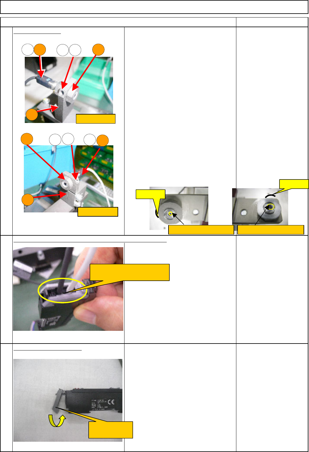
Install the sensor.
1.Insert the plate (D) into the sensor (C)
that has the M6 nut (1). Screw the slit
(A) fully. Unscrew the slit slightly until
the sensor is positioned with its
indication upwards, and the R-shaped
section of the slit is positioned in the
specified position. Fix the sensor with
M6 nut (1).
2. Put a new bushing (2) first. Half
tighten the Hexagon-socket-head
setscrew (3).
<Caution.>
1. Light-emitting: Indication in red
Light-sensing : Indication in blue
2. Slits are different between light-
emitting and -sensing sides. (See
pictures)
3. For the position of the R-shaped
section of the slit, see the pictures.
(1) M6 nut
(2) Bushing
(3) Hexagon-socket-head
setscrew M3 x 4L
A: Slit (light-emitting)
B: Slit (light-sensing)
C: Sensor
D: Plate
Allen key M2
Wrench 10 mm
Wrench 12 mm
13
Close the connector lock.
14
12
Insert the sensor cables into the amplifier connector lock.
R-shaped
Light-sensing
Light-emitting
C B1
2 3
D
D
C
1
3
2
A
R-shaped
Large slit: light-emittingSmall slit: light-sensing
Insert the sensor cables into
the amplifier connector lock.
Close the
connector lock.
EJM8A-E-SMA060405-A01-00
Page 6-4-5-5
Remark
Component-Thickness-Measuring Unit
Item
Option Part and Accessory Replacement
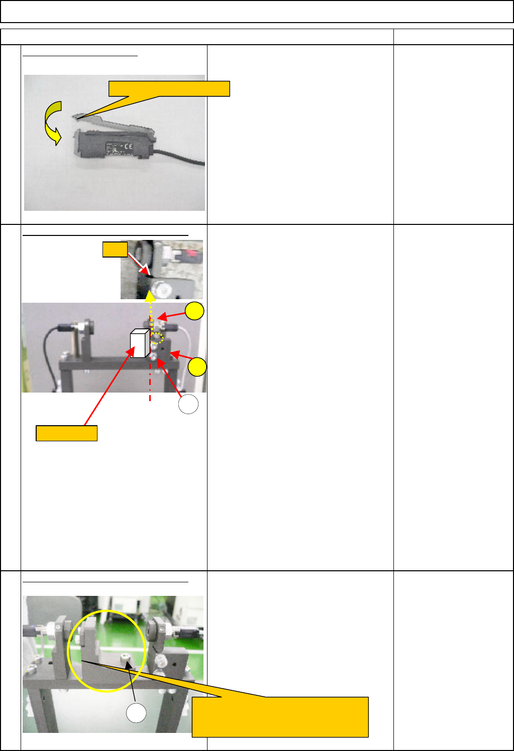
Close the amplifier cover.
15
Light-axis adjustment (Preparation 1)
1. Adjust the gap between the block A
and the plate B,using the adjusting bolts
(1) until the gap becomes 0.
2. Keeping the gap 0, press the block
gauge (10 mm) against the reference
surfaces of the block A and the block B.
Level the block A and the plate B by
aligning them with the block gauge. Fix
them by tightening the adjusting bolts
(1).
<Caution>
Basically it is not necessary to position
the light-sensing plate.
(1) M4 x 16L (2 pcs.)
A: Block
B: Plate
Block gauge (10 mm)
Light-axis adjustment (Preparation 2)
Fix the (2. component-thickness-
measuring-unit-light-axis-adjusting jig) in
place with the bolt (1).
(1) M4 x 16L
FM-1962(2)
(2. Component-thickness-
measuring-unit-light-axis-
adjusting jig)
16
17
A
1
FM-1962(2)
Component-thickness-measuring-unit-
light-axis-adjusting jig
Close the amplifier cover.
1
B
Block gauge
Gap
EJM8A-E-SMA060405-A01-00
Page 6-4-5-6