CM602all_EJM8AESM_Service Manual.pdf - 第849页
Remarks Option Part and Accessory Replacement Item PCB-Warp-Sensor Unit Secure the amplifier cable. - (2) Connect the amplifier connector. * Amplifier connector CN13 Put the head upper cover back on. Phillips screwdriver…
Remarks
Option Part and Accessory Replacement
Item
PCB-Warp-Sensor Unit
Remove the amplifier.
Wrench M4
Hexagon bolt M4
Install the new amplifier.
Wrench M4
Hexagon bolt M4
Connect the connector.
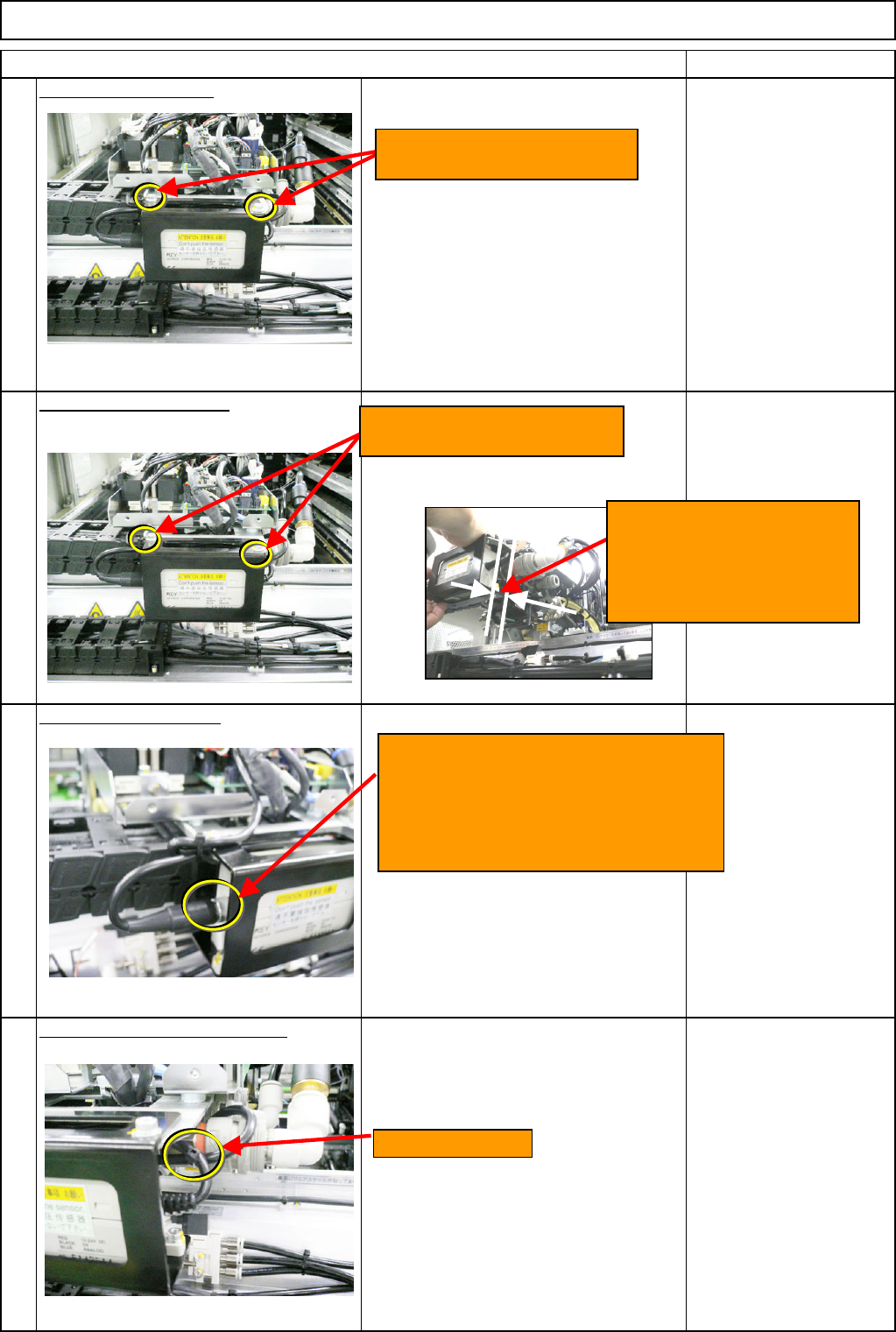
Secure the amplifier cable. - (1)
* Put the cable behind the amplifier, and
to the left. Secure the cable at the
specified position with a cable tie.
12
10
11
9
Cable-tie position
Loosen the two M4x12L bolts.
Remove the amplifier.
Tighten the two M4x12L bolts.
Install the new amplifier.
<Caution>
Create a 2-mm gap between
the amplifier and the plate
when installing the amplifier.
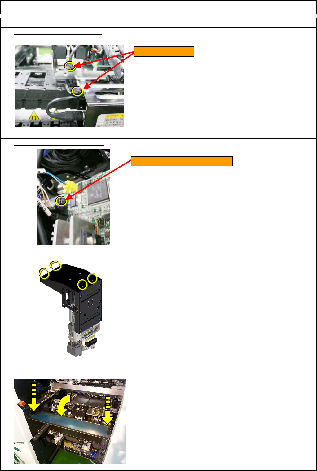
Insert the sensor connector (To
amplifier), aligning the pin position.
Turn the cap screw, which is positioned
at the end of the cable, to the right. Fix
it in place.
EJM8A-E-SMA060502-A01-01
Page 6-5-2-4
Remarks
Option Part and Accessory Replacement
Item
PCB-Warp-Sensor Unit
Secure the amplifier cable. - (2)
Connect the amplifier connector.
* Amplifier connector CN13
Put the head upper cover back on.
Phillips screwdriver #2
Truss M4 screw 4 pcs.
Put the feeder cover back on.
Allen key 3 mm
Screw M4 4 pcs.
13
14
15
16
Cable-tie positions
Connect the amplifier connector.
EJM8A-E-SMA060502-A01-01
Page 6-5-2-5
Remarks
Option Part and Accessory Replacement
Item
PCB-Warp-Sensor Unit
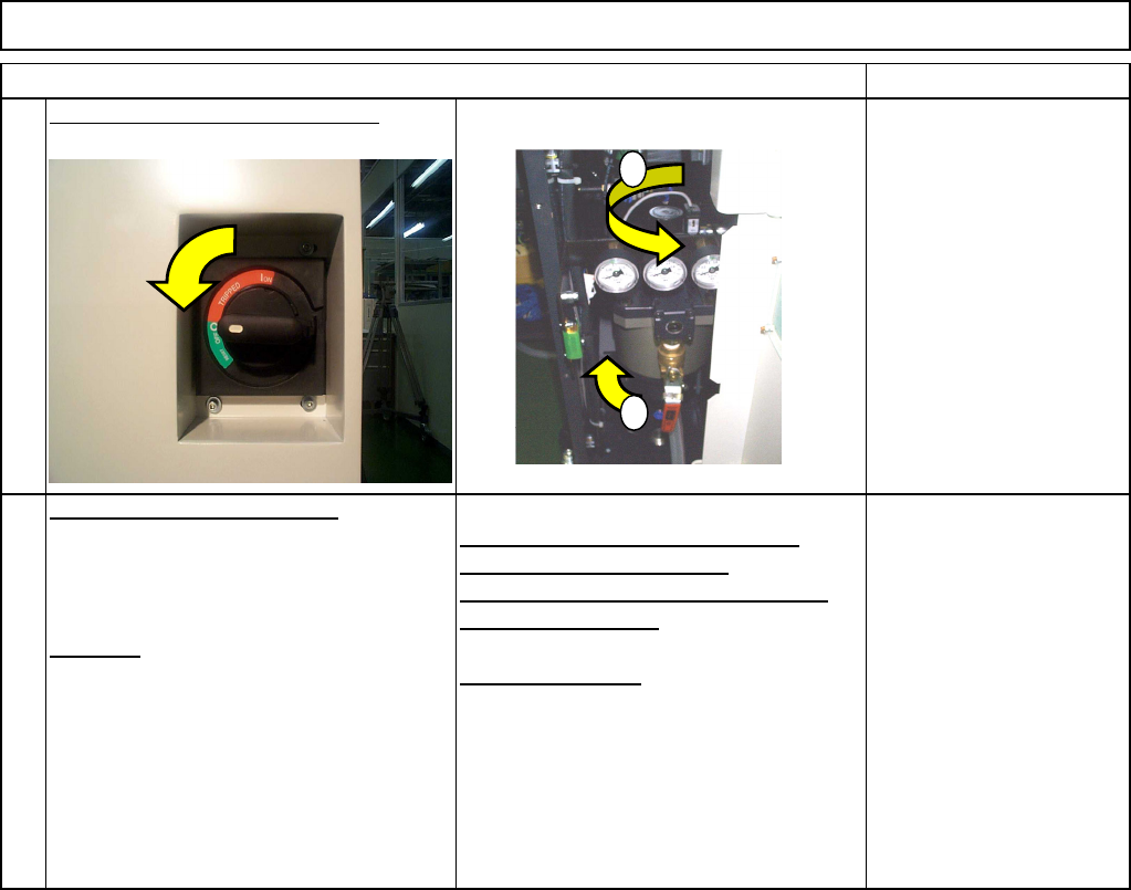
Turn on the power and air supply.
PCB-warp-sensor adjustment
Teaching
Adjusting the amplifier 0 reference
position (0-volt adjustment)
Adjusting the slant (span) of amplifier
(+2-volt adjustment)
XY offset teaching
See Section 6-5-5
17
18
1
2
EJM8A-E-SMA060502-A01-01
Page 6-5-2-6