CM602all_EJM8AESM_Service Manual.pdf - 第861页
Remarks Preparation Turn off the power and air supply. 2 Remove the feeder cover. 3 Allen key 3 mm Screw M4 4 pcs. 4 Item 1 Move the front and rear beams towards you. Option Part and Accessory Replacement PCB-Warp-Sensor…
This section describes the procedures for replacing the PCB-warp sensor (12-nozzle head spec.).
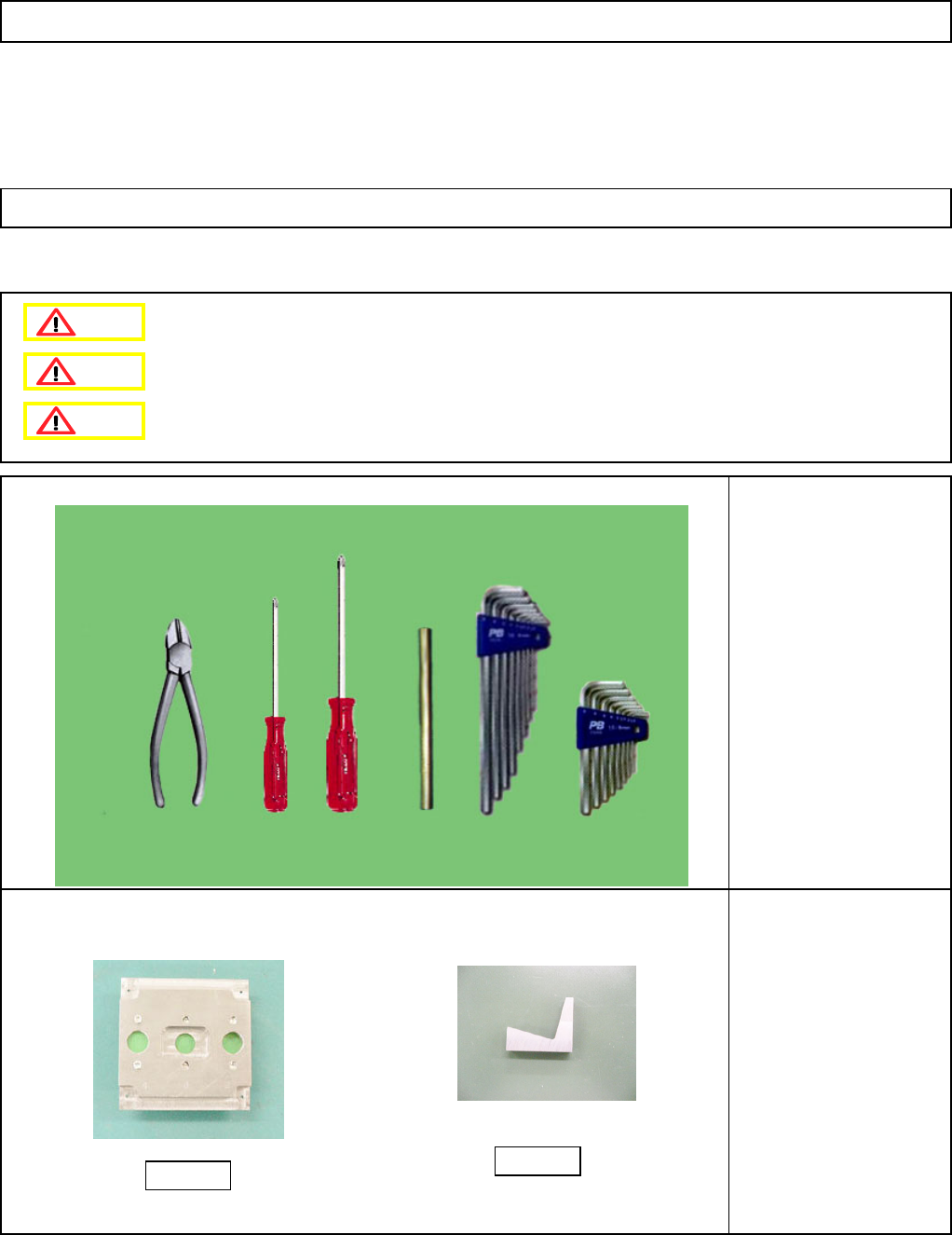
• Tools
Phillips screwdriver #1
Phillips screwdriver #2
Allen key Long/short
Pipe
Nipper
• Jigs
Height measuring jig
FM-1964
Installation adjusting jig
FM-1963
Option Part and Accessory Replacement
PCB-Warp-Sensor Unit
6-5-4 PCB-Warp-Sensor Replacement (12-Nozzle-Head Spec.)
FM-1964
FM-1963
Dange
r
Warning
Caution
EJM8A-E-SMA060504-A01-00
Page 6-5-4-1
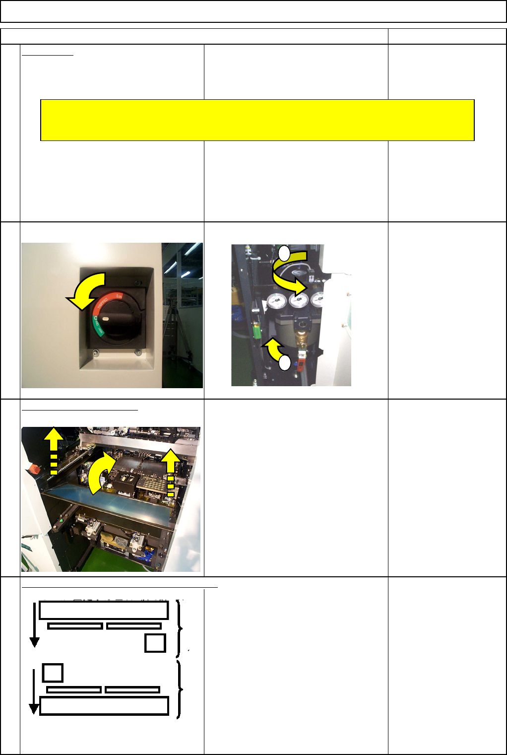
Remarks
Preparation
Turn off the power and air supply.
2
Remove the feeder cover.
3
Allen key 3 mm
Screw M4 4 pcs.
4
Item
1
Move the front and rear beams towards you.
Option Part and Accessory Replacement
PCB-Warp-Sensor Unit
1
2
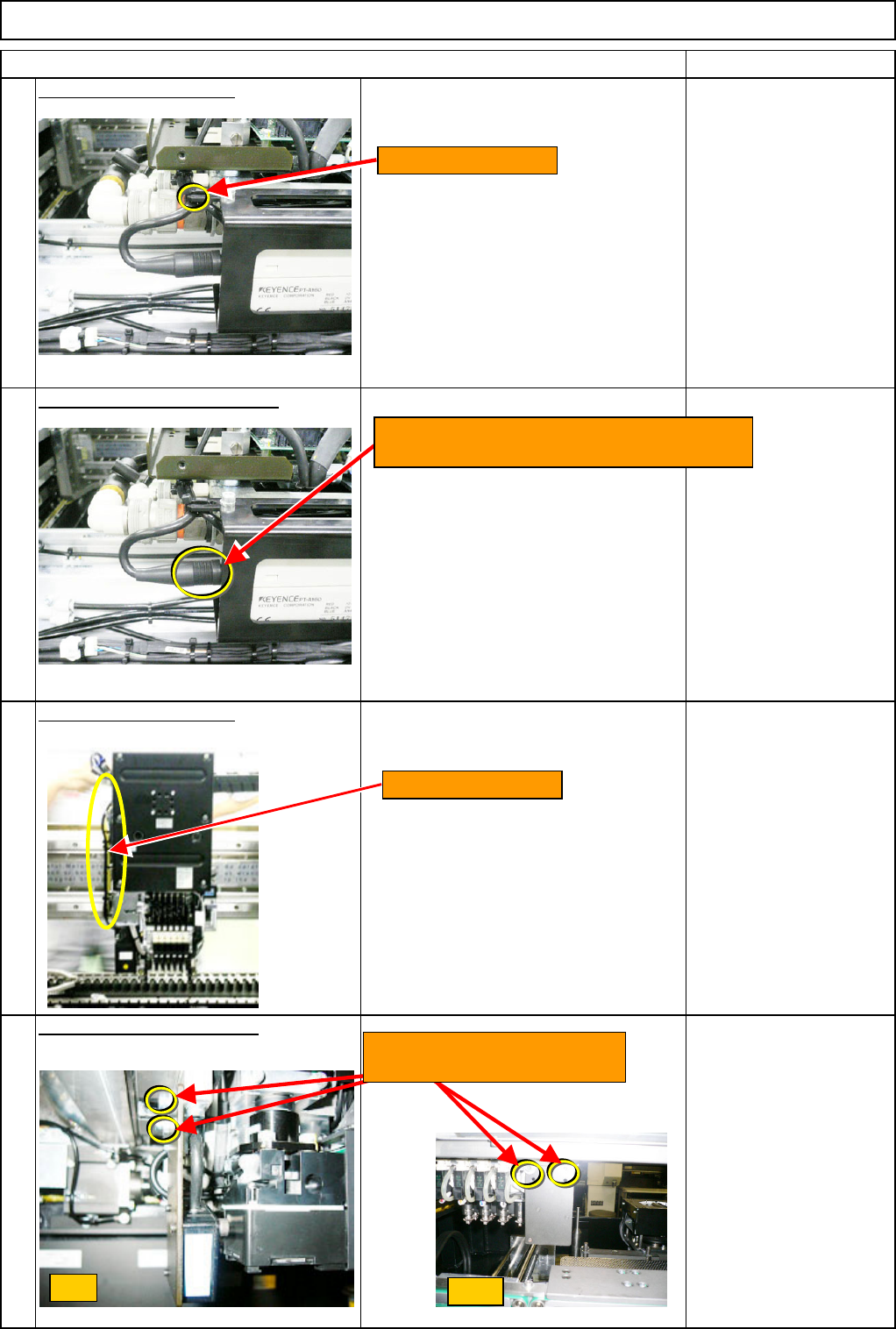
Remove all the support pins.
* Before replacing the sensor, check no polarizing plates are attached to the head camera.
Rear Front
EJM8A-E-SMA060504-A01-00
Page 6-5-4-2
Remarks
Item
Option Part and Accessory Replacement
PCB-Warp-Sensor Unit
Cut off the cable tie. - (1)
Remove the sensor connector.
Cut off the cable tie. - (3)
Remove the sensor bracket.
Wrench M4
M4 x 14L (2 pcs.)
6
5
8
7
Cut off the cable tie.
Turn the sensor connector (to the amplifier)
to the left. Remove the connector.
Cut off the cable tie.
Front
Side
Loosen the two M4x14L bolts.
Remove the bracket.
EJM8A-E-SMA060504-A01-00
Page 6-5-4-3