CM602all_EJM8AESM_Service Manual.pdf - 第911页
When the ball screw is not positioned in the origin, it cannot be removed, so skip this step. Phillips screwdriver #2 Screw M4 12 pcs. Allen key 3 mm Screw M4 4 pcs. Remove the ball screw cover. Remraks Switch off the po…
30 8050
Lift-axis Motor Replacement
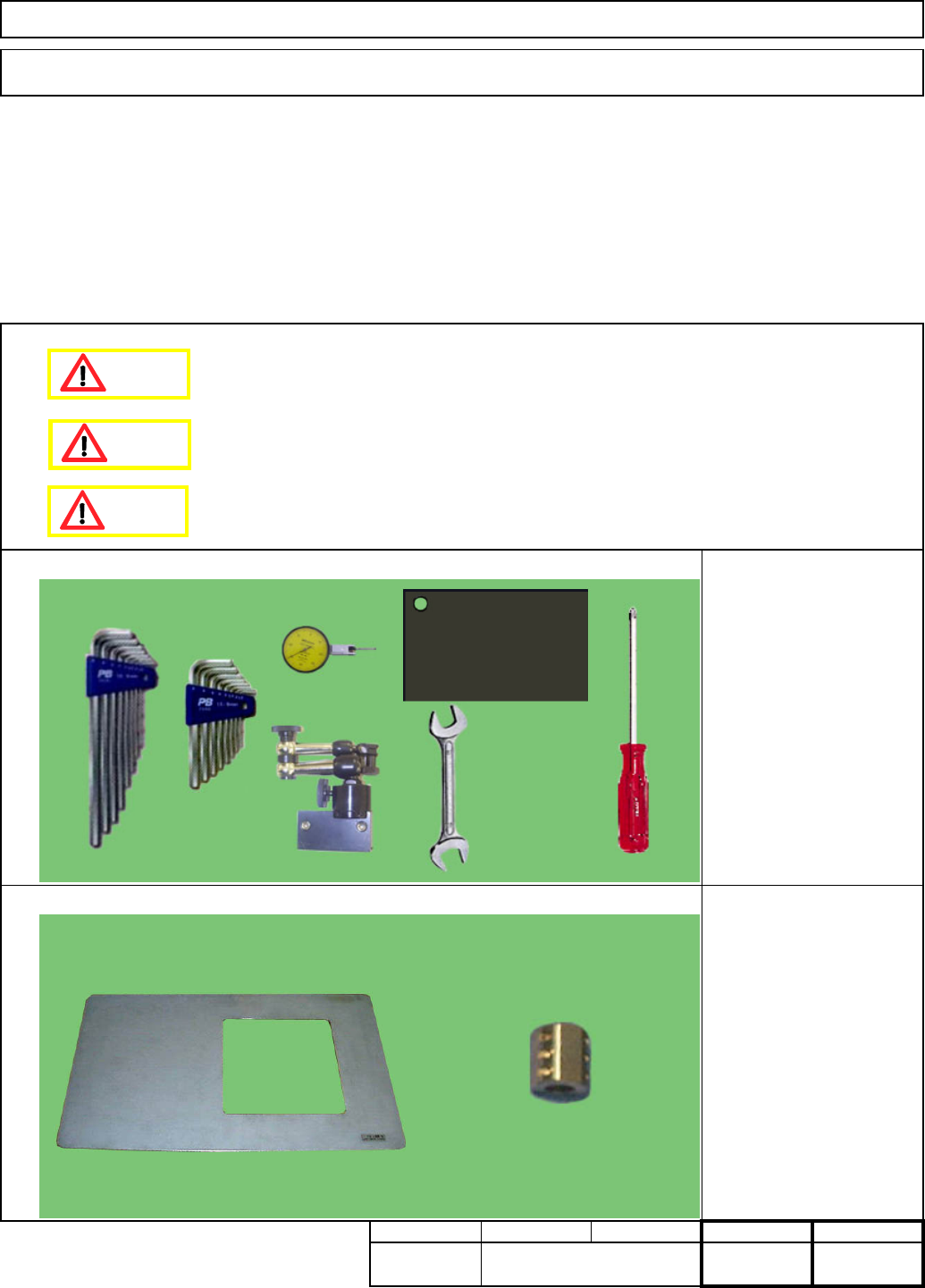
Phillips screwdriver #2
Allen key 3 mm
Allen key 5 mm
Wrench 14 mm
Dial gauge
Magnetic stand
Magnetic stand holding iron
plate
This section describes the procedures for replacing the lift-axis motor.
Alignment jig
FM-0558: Palette jig
Tray Shuttle Tray
Min. Min. Min. kgs.
7-1-6
Tools
Jigs
Removal/Disassembly Assembly/Adjustment
Teaching
Total Part Weight
Min.
Dange
r
Caution
Warning
EJM8A-E-SMA070106-A01-00
Page 7-1-6-1
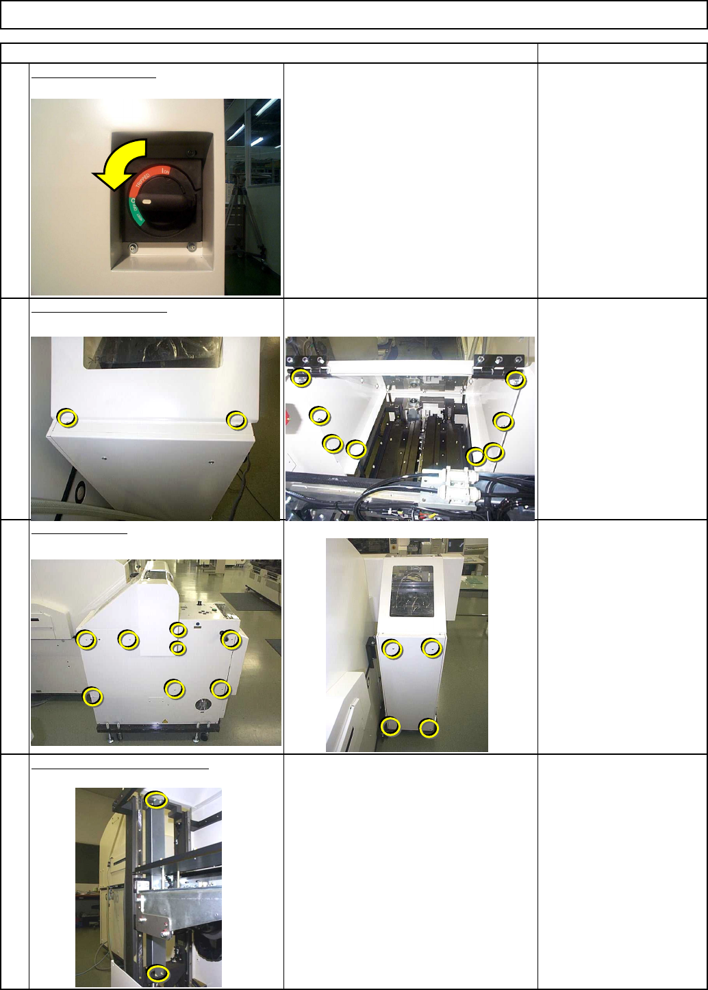
When the ball screw is not positioned
in the origin, it cannot be removed, so
skip this step.
Phillips screwdriver #2
Screw M4 12 pcs.
Allen key 3 mm
Screw M4 4 pcs.
Remove the ball screw cover.
Remraks
Switch off the power.
1
Item
Remove the top cover.
2
3
4
Phillips screwdriver #2
Allen key 3 mm
Screw M4 2 pcs.
M4×10L 8 pcs.
Tray Shuttle Tray
Open the cover.
EJM8A-E-SMA070106-A01-00
Page 7-1-6-2
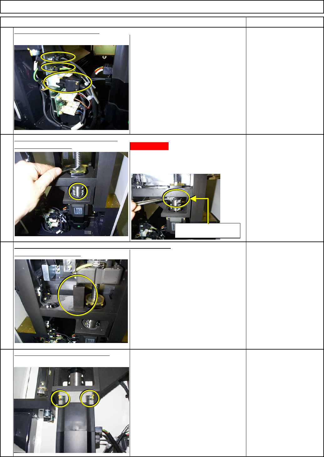
Lift will Fall!
When the coupling is loosened, the lift
will fall down. To avoid this, hold the
ball screw with a wrench.
Block (Not designated)
Remove the motor connectors.
Allen key 5 mm
Screw M5 4 pcs.
Remove the motor holding screws.
5
Item
Allen key 4 mm
Wrench 14 mm
Screw M5 6 pcs.
After removing the coupling, hold the lift-axis with a block,
remove the coupling.
6
7
8
Tray Shuttle Tray
Remraks
Holding the ball screw with a wrench,
and remove the wrench.
If the cover cannot be
removed
,
hold here.
EJM8A-E-SMA070106-A01-00
Page 7-1-6-3