CM602all_EJM8AESM_Service Manual.pdf - 第917页
Assembly/Adjustment Removal/Disassembly 15 Min. Min. 30 Total Part Weight Phillips screwdriver #2 Allen key 3 mm Ruler 150 mm Ruler 300 mm kgs. 45 Min. Connector jig 7-1-7 Shuttle Head Stroke Adjustment Shuttle Tray Tool…
Item Remraks
21
Specifications:
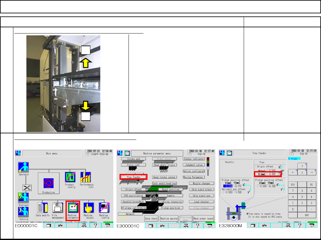
±1.0 mm or less
After tightening the coupling, confirm the height.
Enter the measured value into [TL] manually.
22
Tray Shuttle Tray
+
-
EJM8A-E-SMA070106-A01-00
Page 7-1-6-7
Assembly/AdjustmentRemoval/Disassembly
15
Min. Min.
30
Total Part Weight
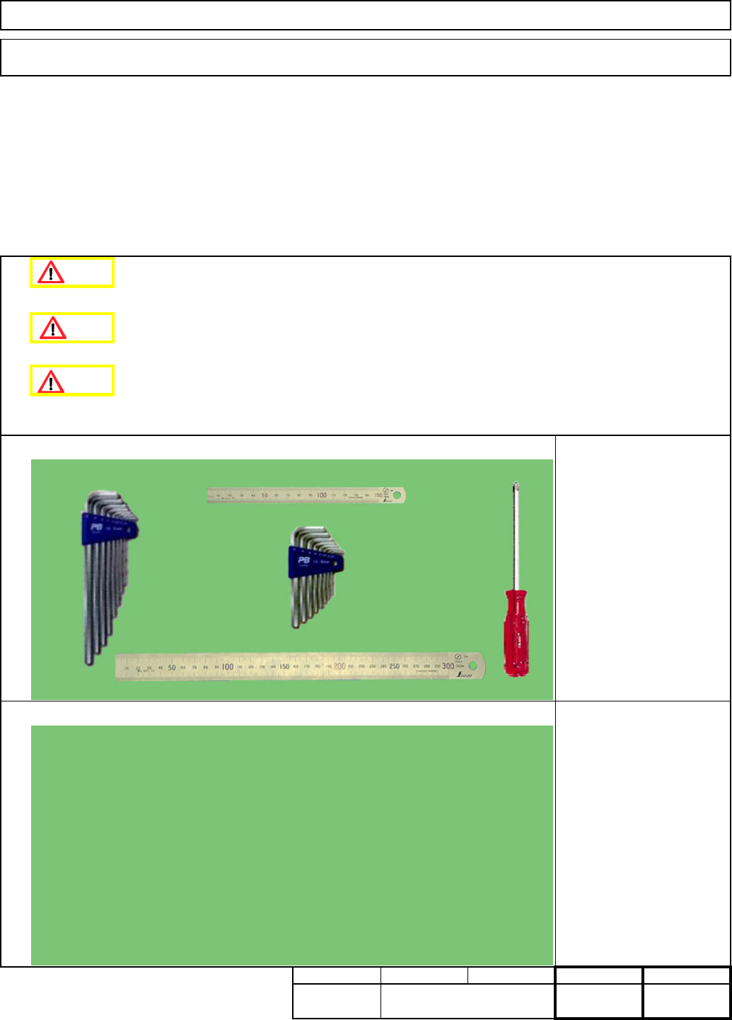
Phillips screwdriver #2
Allen key 3 mm
Ruler 150 mm
Ruler 300 mm
kgs.
45
Min.
Connector jig
7-1-7 Shuttle Head Stroke Adjustment
Shuttle Tray
Tools
Tray
・This section describes the procedures for adjusting the stroke of the shuttle head.
I Since this adjustment requires releasing the safety cover switch, only those who are authorized
to release it based on the Document "Key Switch/Key Disk Receipt Confirmation and Safety
Precautions" are permitted to perform this adjustment.
Jigs
Min.
Teaching
Danger
Caution
Warning
EJM8A-E-SMA070107-A01-00
Page 7-1-7-1
12
34
Remarks
4
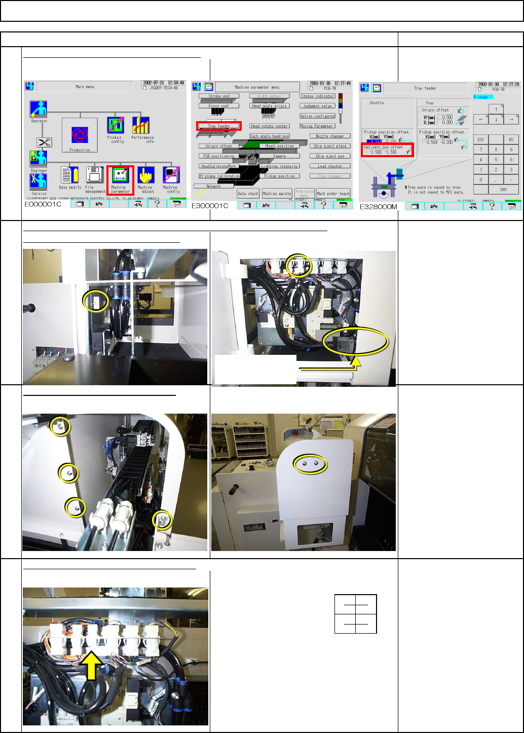
Fit the jig on the door switch connector.
Allen key 3 mm
M4 x 10L 1 pc.
Allen key 3 mm
Phillips screwdriver #2
M4×8L 3 pcs.
M4×10L 2 pcs.
M5×15L Truss 2 pcs.
Open the cover of the delivery position. Open the maintenance door.
Set the machine parameter offset to "0."
Tray
3
Remove the cover holding screws.
Shuttle Tray
2
1
Item
Remove the door switch connector.
Door switch of
Delivery position
EJM8A-E-SMA070107-A01-00
Page 7-1-7-2