CM602all_EJM8AESM_Service Manual.pdf - 第928页
Item Remarks Shuttle Tray Tray Allen key 3 mm Phillips screwdriver #2 M4×8L 3 pcs. M4×10L 2 pcs. M5×15L Truss 2 pcs. 21 Put the top cover back on. Allen key 3 mm Phillips screwdriver #2 M4×8L 8 pcs. M4×10L Truss 2 pcs. S…
12
34
Remarks
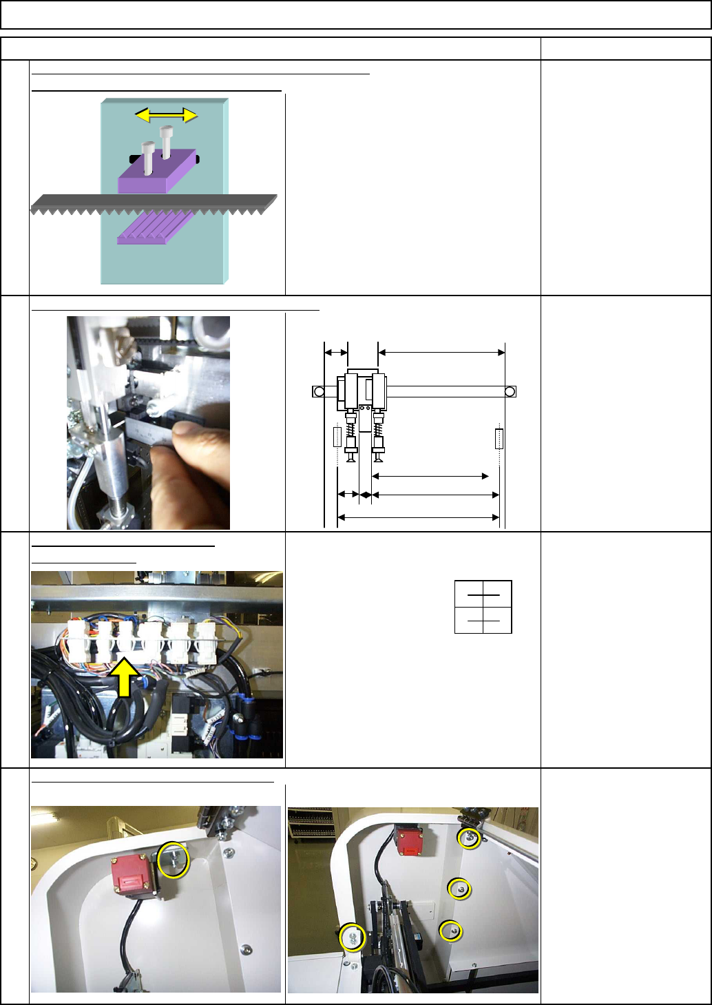
loosen the bolts below and move the belt.
Shuttle TrayTray
Allen key 3 mm
Screw M4 2 pcs.
If it is necessary to adjust the distance more than 3 mm,
19
20
Item
18
17
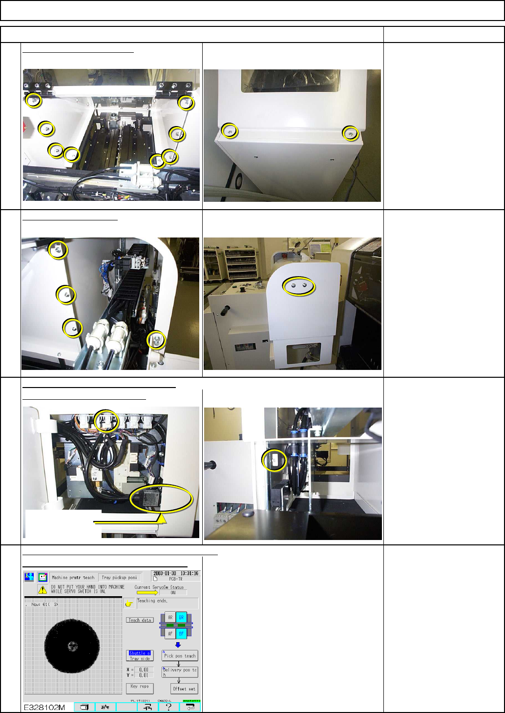
Carry out "Return to origin." Check the distance.
Remove the jig from the door
switch connector.
Allen key 3 mm
M4×8L 3 pcs.
M4×10L 2 pcs.
M4×12L 2 pcs.
Put the cover back on the motor section.
30
B
A=727st
(770)
C
D
E
EJM8A-E-SMA070108-A01-00
Page 7-1-8-6
Item Remarks
Shuttle TrayTray
Allen key 3 mm
Phillips screwdriver #2
M4×8L 3 pcs.
M4×10L 2 pcs.
M5×15L Truss 2 pcs.
21
Put the top cover back on.
Allen key 3 mm
Phillips screwdriver #2
M4×8L 8 pcs.
M4×10L Truss 2 pcs.
See Section 7-1-2. "Shuttle
Tray Pickup Position
Teaching."
23
Close the maintenance door.
Allen key 3 mm
M4 x 10L 1 pc.
Connect the door switch connector.
24
22
Put the cover back on.
Once the mechanical adjustment is complete,
carry out machine parameter teaching.
Door switch of
Delivery position
EJM8A-E-SMA070108-A01-00
Page 7-1-8-7
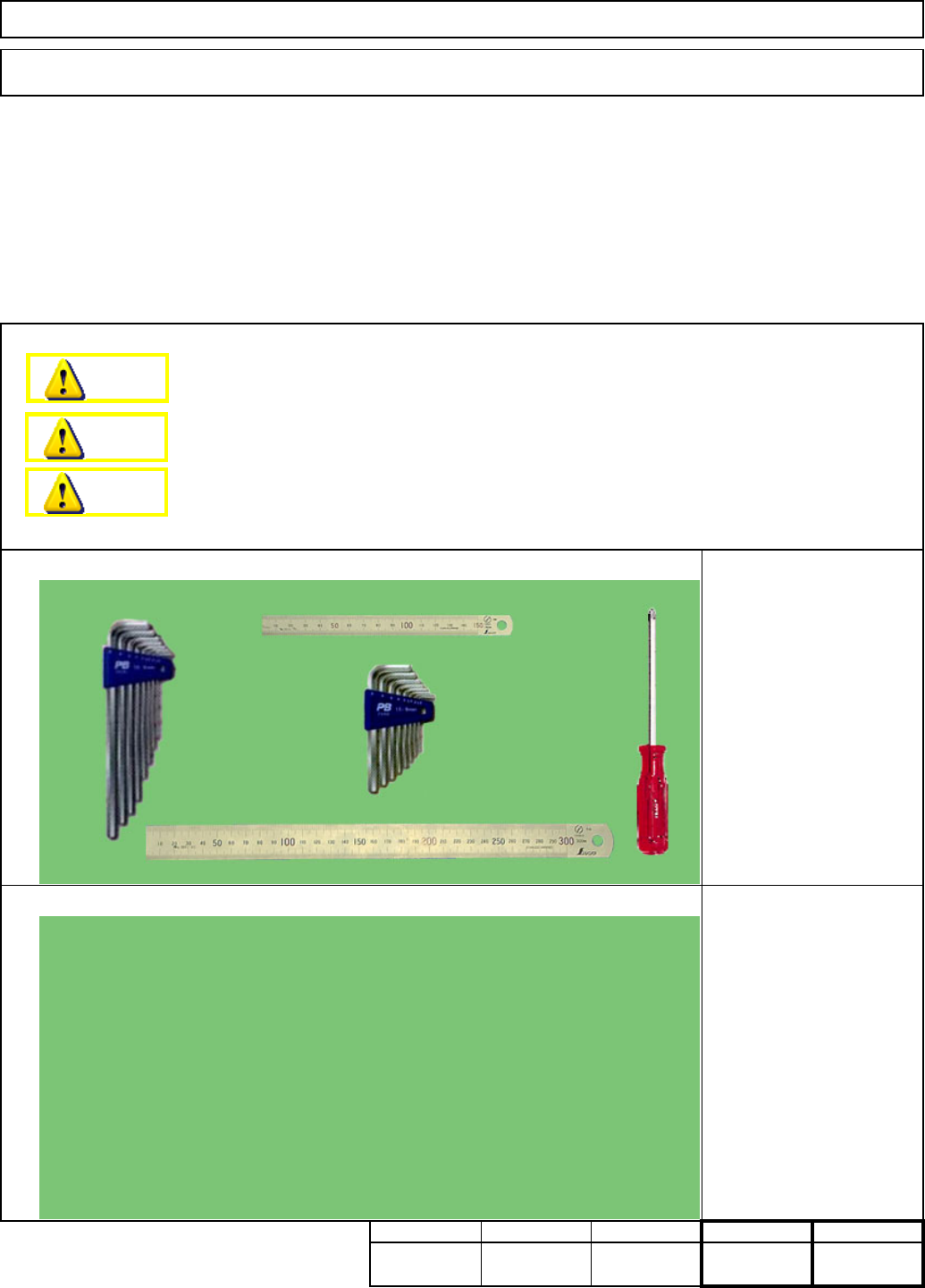
Teaching
Tools
Jigs
Min. Min.
25
Connector jig
Phillips screwdriver #2
Allen key 3 mm
Allen key 4 mm
Ruler 150 mm
Ruler 300 mm
kgs.
75
Min.Min.
35
This section describes the procedures for replacing the shuttle head motor.
Total Part Weight
Assembly/AdjustmentRemoval/Disassembly
15
7-1-9 Shuttle Head Motor Replacement
Shuttle TrayTray
Dange
r
Warning
Caution
EJM8A-E-SMA070109-A01-00
Page 7-1-9-1