CM602all_EJM8AESM_Service Manual.pdf - 第938页
After loosening the power locks, hit them lightly to remove them. Tray Shuttle Tray Move the extension-axis forwards by 436.5 st. 4 Remarks Item Open the side cover Phillips screwdriver #2 Screw M4 8 pcs. 2 1 Allen key 4…
Tray Shuttle Tray
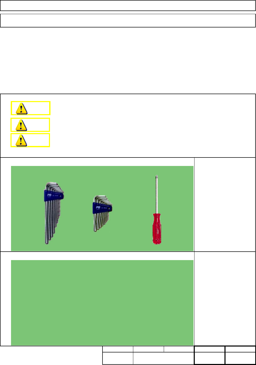
Tools
Jigs
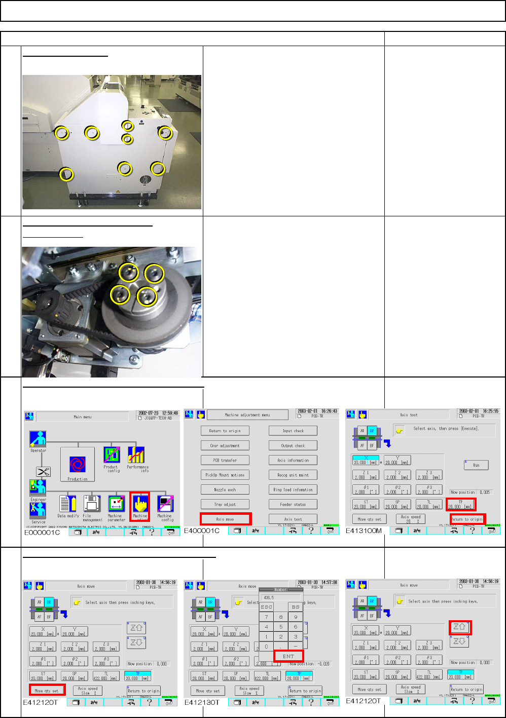
Removal/Disassembly
7-1-10 Extension-Axis Stroke Adjustment
This section describes the procedures for adjusting the stroke of the extension-axis.
Jig: FM-0982
Min.
Part Weight
Assembly/Adjustment
Teaching
Total
Min.
Phillips screwdriver #2
Allen key 2.5 mm
Allen key 4 mm
kgs.
0
Min. Min.
Dange
r
Warning
Caution
EJM8A-E-SMA070110-A01-00
Page 7-1-10-1
After loosening the power locks,
hit them lightly to remove them.
Tray Shuttle Tray
Move the extension-axis forwards by 436.5 st.
4
RemarksItem
Open the side cover
Phillips screwdriver #2
Screw M4 8 pcs.
2
1
Allen key 4 mm
Screw M5 4 pcs.
Return the extension-axis (TL) to the origin.
Loosen the power locks of the
motor section
.
3
436.5
EJM8A-E-SMA070110-A01-00
Page 7-1-10-2
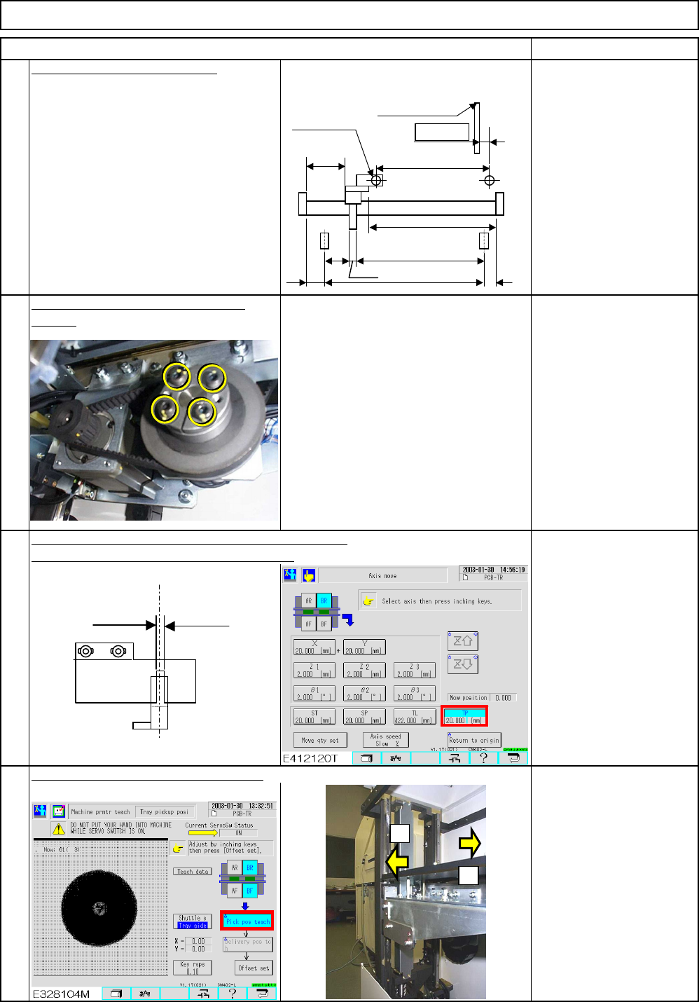
Tighten the power locks of the motor
Tray Shuttle Tray
6
RemarksItem
5
Position the slit of the dog slit in the extension position.
Inch the extension-axis (One inching: 0.1mm)
See Section 7-1-2 "Shuttle
Tray Pickup Position
Teaching."
Carry out the 'Pickup position" teaching.
8
7
Allen key 4 mm
Screw M5 4 pcs.
Jig: FM-0982
Allen key 2.5 mm
Screw M3 2 pcs.
section.
Position the bearing with the jig.
+
-
A=436.5 st
Origin
E
CD
(454.5)
8
F
B=11.0
Shutter
(2)
(73)
Magazine side
(0.5㎜)
Lift side
(1.0㎜)
Light beam sensor
Extension position
PH sensor
Dog
EJM8A-E-SMA070110-A01-00
Page 7-1-10-3