CM602all_EJM8AESM_Service Manual.pdf - 第945页
Item Remarks 13 Move the extension-axis forward by 436.5 st. Allen key 2.5 mm Screw M3 2 pcs. Allen key 4 mm Screw M5 4 pcs. Position the bearing with the jig. Jig: FM-0982 16 Position the slit of the dog slit in the ext…
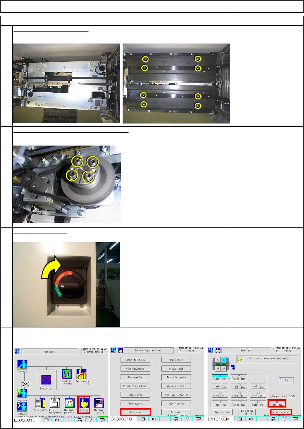
After loosening the motor locks,
hit them lightly to remove them.
Item Remarks
Allen key 2.5 mm
M3 8 pcs.
9
Put the palette table back on.
Loosen the power locks at the motor section.
10
11
12
Allen key 4 mm
Screw M5 4 pcs.
Switch on the power.
Tray Shuttle Tray
Return the extension-axis to the origin.
EJM8A-E-SMA070111-A01-00
Page 7-1-11-4
Item Remarks
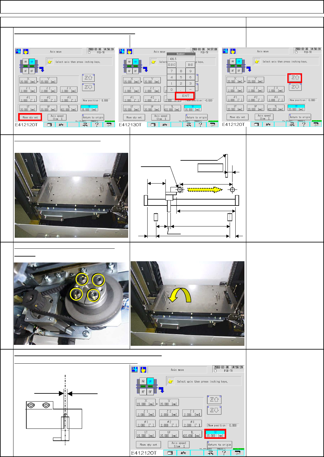
13
Move the extension-axis forward by 436.5 st.
Allen key 2.5 mm
Screw M3 2 pcs.
Allen key 4 mm
Screw M5 4 pcs.
Position the bearing with the jig.
Jig: FM-0982
16
Position the slit of the dog slit in the extension position.
Inch the extension-axis (One inching: 0.1mm)
section.
14
15
Tighten the power locks of the motor
Tray Shuttle Tray
436.5
A=436.5 st
Origin
E
CD
(454.5)
8
F
B=11.0
Shutter
(2)
(73)
Magazine side
(0.5㎜)
Lift side
(1.0㎜)
Light beam sensor
Extension position
PH sensor
Dog
EJM8A-E-SMA070111-A01-00
Page 7-1-11-5
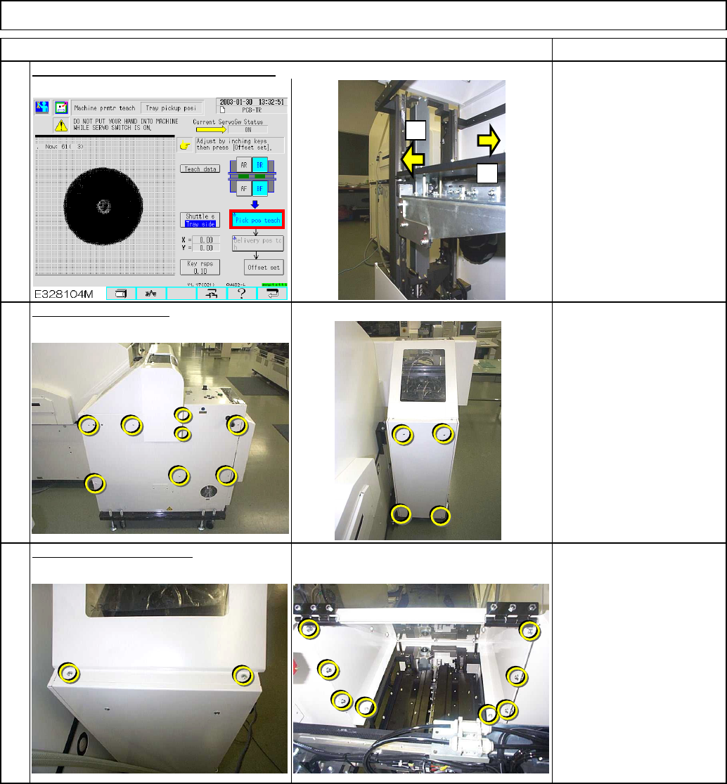
See Section 7-1-2 "Shuttle
Tray Pickup Position
Teaching."
Carry out the 'Pickup position" teaching.
Phillips screwdriver #2
Screw M4 12 pcs
17
Phillips screwdriver #2
Allen key 3 mm
Screw M4 2 pcs.
M4x10L 8 pcs.
Remarks
Shuttle Tray
19
Put the top cover back on.
Item
18
Put the cover back on.
Tray
+
-
EJM8A-E-SMA070111-A01-00
Page 7-1-11-6