CM602all_EJM8AESM_Service Manual.pdf - 第959页
21 Put the upper cover back on. Phillips screwdriver #2 Allen key 3 mm Screw M4 2 pcs. M4 x 10L 8 pcs. Item Remarks Tray Shuttle Tray EJM8A-E-SMA070113-A01-00 Page 7-1-13-7
Tray
20
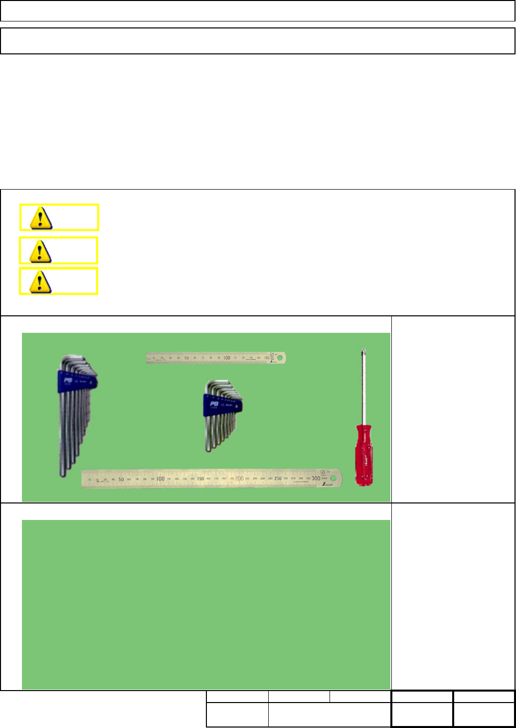
Put the cover back on.
Phillips screwdriver #2
Screw M4 12 pcs.
19
Teach pickup position.
See Section "7-1-2. Shuttle
Tray Teaching."
18
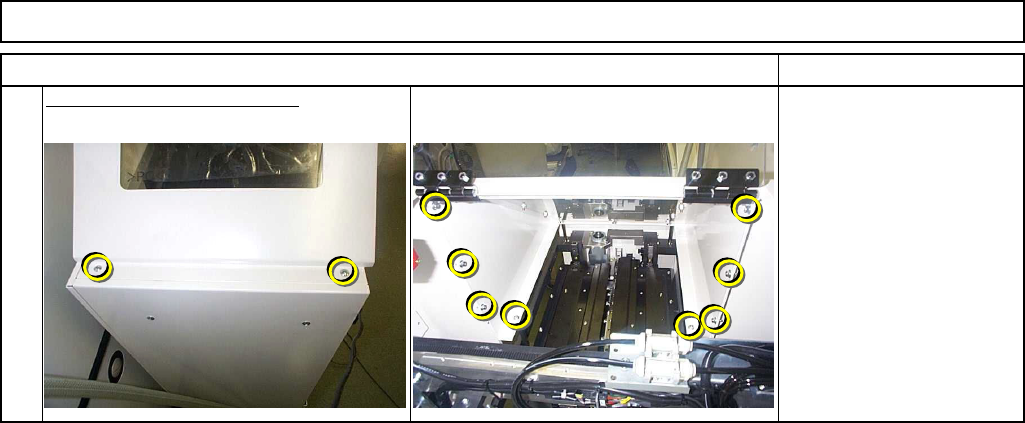
Inch the dog by 0.1 mm.
Allen key 2.5 mm
Screw M3 2 pcs.
Precisely position the slit of the jig at the extension position.
17
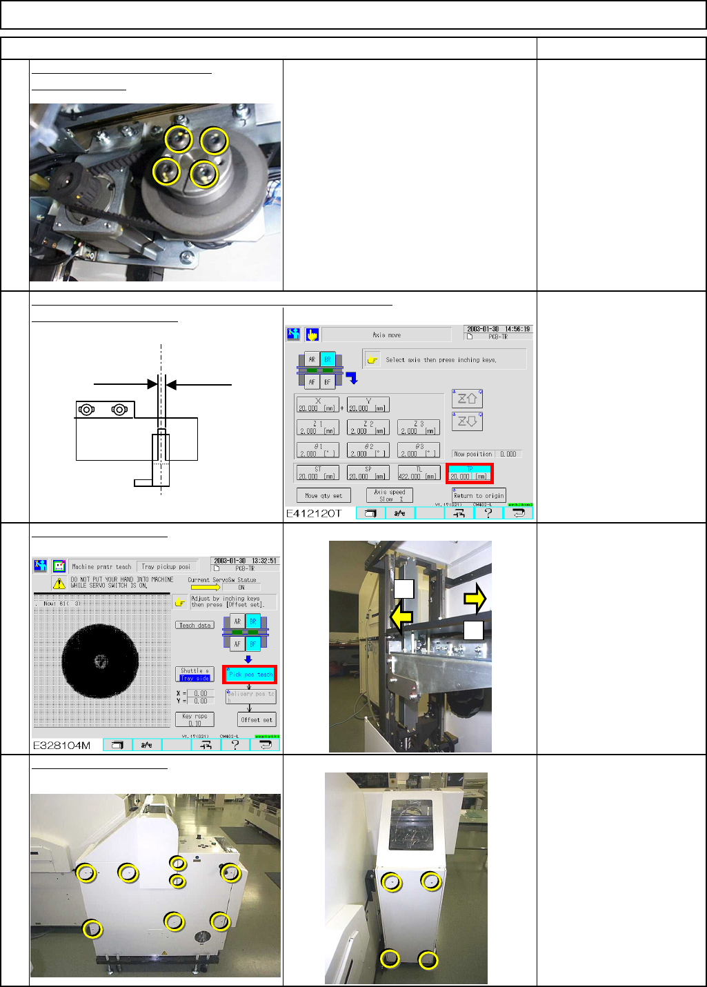
Tighten the motor power lock.
Remove the jig.
Allen key 4 mm
Screw M5 4 pcs.
Item Remarks
Shuttle Tray
+
-
Magazine side
(0.5 mm)
Lift side
(1.0 mm)
Light-axis sensor
Extension position
PH sensor
Dog
EJM8A-E-SMA070113-A01-00
Page 7-1-13-6
21
Put the upper cover back on.
Phillips screwdriver #2
Allen key 3 mm
Screw M4 2 pcs.
M4 x 10L 8 pcs.
Item Remarks
Tray Shuttle Tray
EJM8A-E-SMA070113-A01-00
Page 7-1-13-7
This section describes the procedures for adjusting the stroke of the transfer unit.
7-1-14 Transfer Unit Stroke Adjustment
Phillips screwdriver #2
Allen key 3 mm
Ruler 150 mm
Ruler 300 mm
None
min. min.
kgs.
35
min.min.
1520
Shuttle TrayTray
Tools
Jigs
Removal/Disassembly Assembly/Adjustment
Teaching
Total Part Weight
Dange
r
Warning
Caution
EJM8A-E-SMA070114-A01-00
Page 7-1-14-1