CM602all_EJM8AESM_Service Manual.pdf - 第969页
7-1-16 Head LED Sensor Replacement Shuttle Tray Tray This section describes the procedures for replacing the head LED sensor. Total Part Weight Assembly/Adjustment Removal/Disassembly 7 8 Min. 15 Pickup position adjustme…
Tray
Item Remark
13
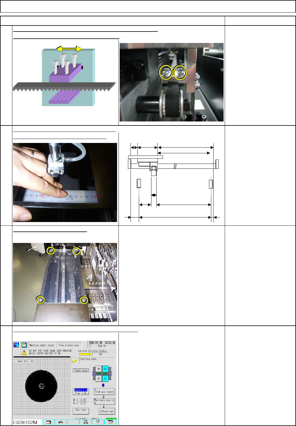
again. Measure the clearance again.
14
Phillips screwdriver #2
Truss screw 4 pcs.
Allen key 2.5 mm
Screw M3 2 pcs.
Shuttle Tray
16
See Section "7-1-2.
Shuttle Tray Teaching."
15
Put the upper cover back on.
Carry out the "return-to-origin" operation
After the adjustment, teach machine parameters.
If it is necessary to adjust the distance more than 3 mm,
loosen the bolts below and move the belt.
22
B
A=550st
(587)
C
D
E
(67)
(8.5)
(46.5)
EJM8A-E-SMA070115-A01-00
Page 7-1-15-5
7-1-16 Head LED Sensor Replacement
Shuttle TrayTray
This section describes the procedures for replacing the head LED sensor.
Total Part Weight
Assembly/AdjustmentRemoval/Disassembly
78
Min.
15
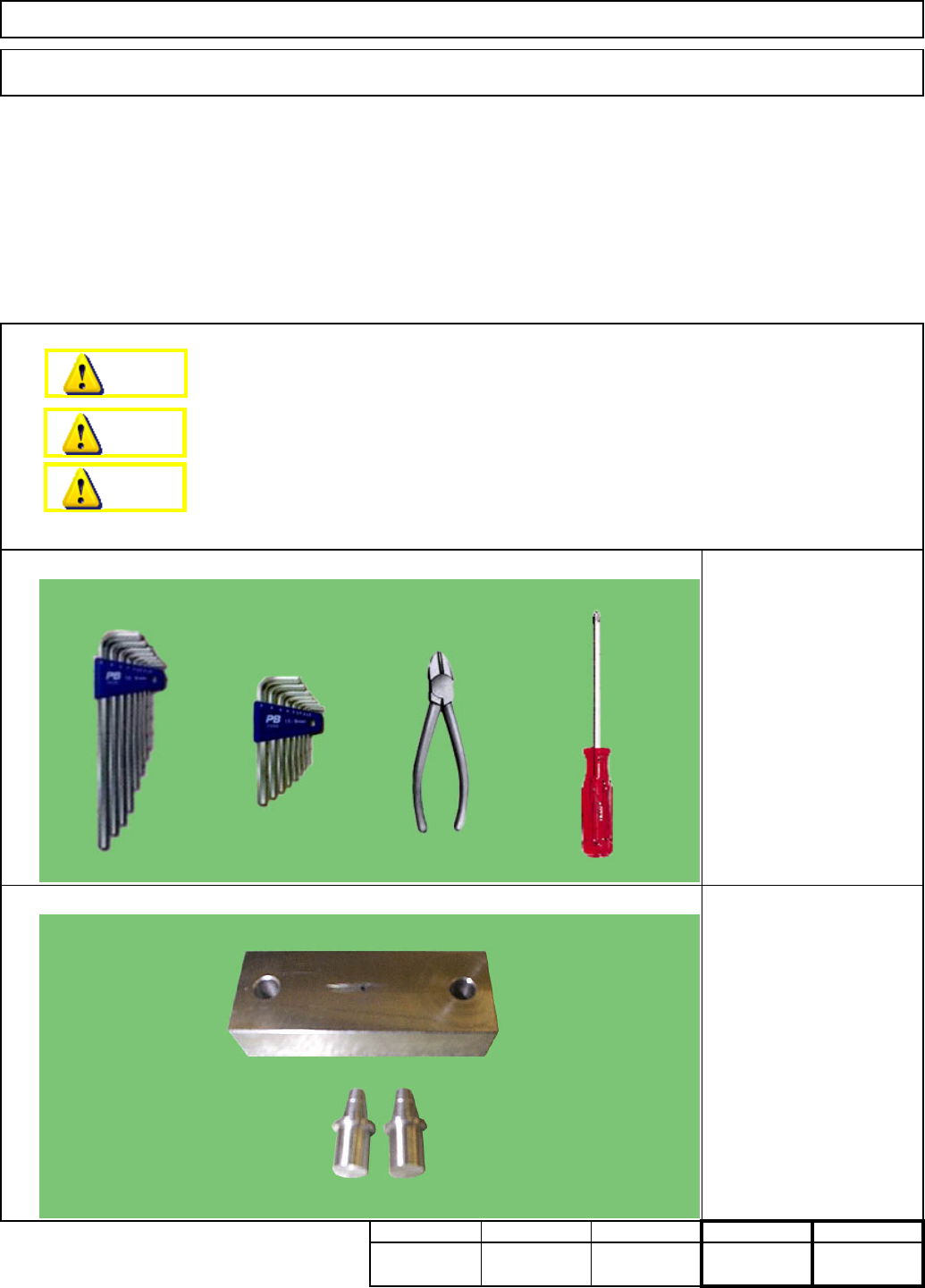
Pickup position adjustment
jig
Nozzle jig
Allen key 2.5 mm
Allnen key 3 mm
Phillips screwdriver #2
Nipper
Teaching
Tools
Jigs
Min. Min. kgs.
30
Min.
Dange
r
Warning
Caution
EJM8A-E-SMA070116-A01-00
Page 7-1-16-1
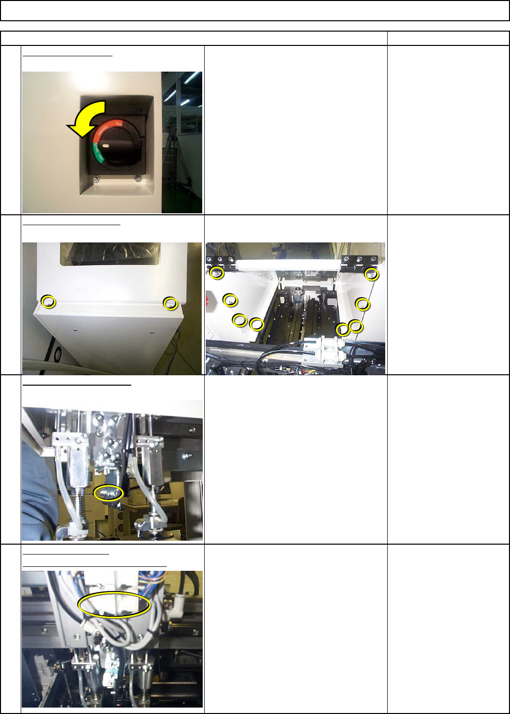
Disconnect the sensor connector.
3
4
2
1
Cut off the cable tie.
Remove the LED sensor.
Remove the top cover.
Phillips screwdriver #2
Allen key 3 mm
Screw M4 2 pcs.
M4 x 10L 8 pcs.
Nipper
Remarks
Allen key 2.5 mm
Screw M3 2 pcs.
Switch off the power.
Item
Shuttle TrayTray
EJM8A-E-SMA070116-A01-00
Page 7-1-16-2