CM602all_EJM8AESM_Service Manual.pdf - 第976页
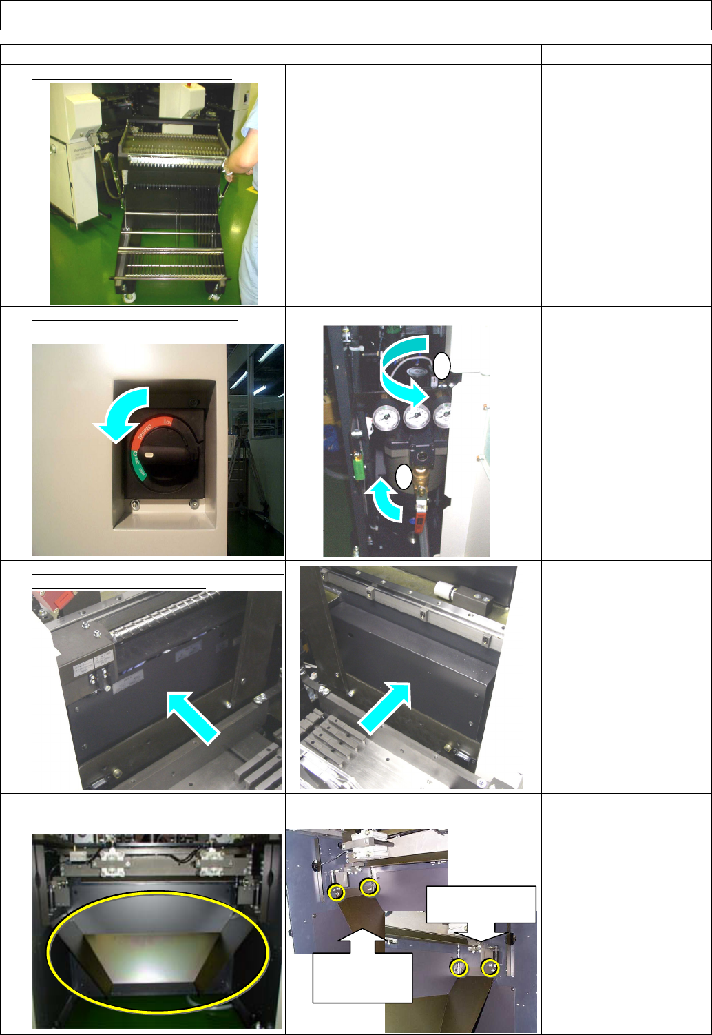
Remove the side covers from the feeder section. ( AR and BR sta g es ) Tray 4 2 1 Item Turn off the power and air supply. Remarks Remove all feeder change carts. 3 Shuttle Tray Remove all lower chutes. Allen key 4 mm M5 …
Assembly/Adjustment
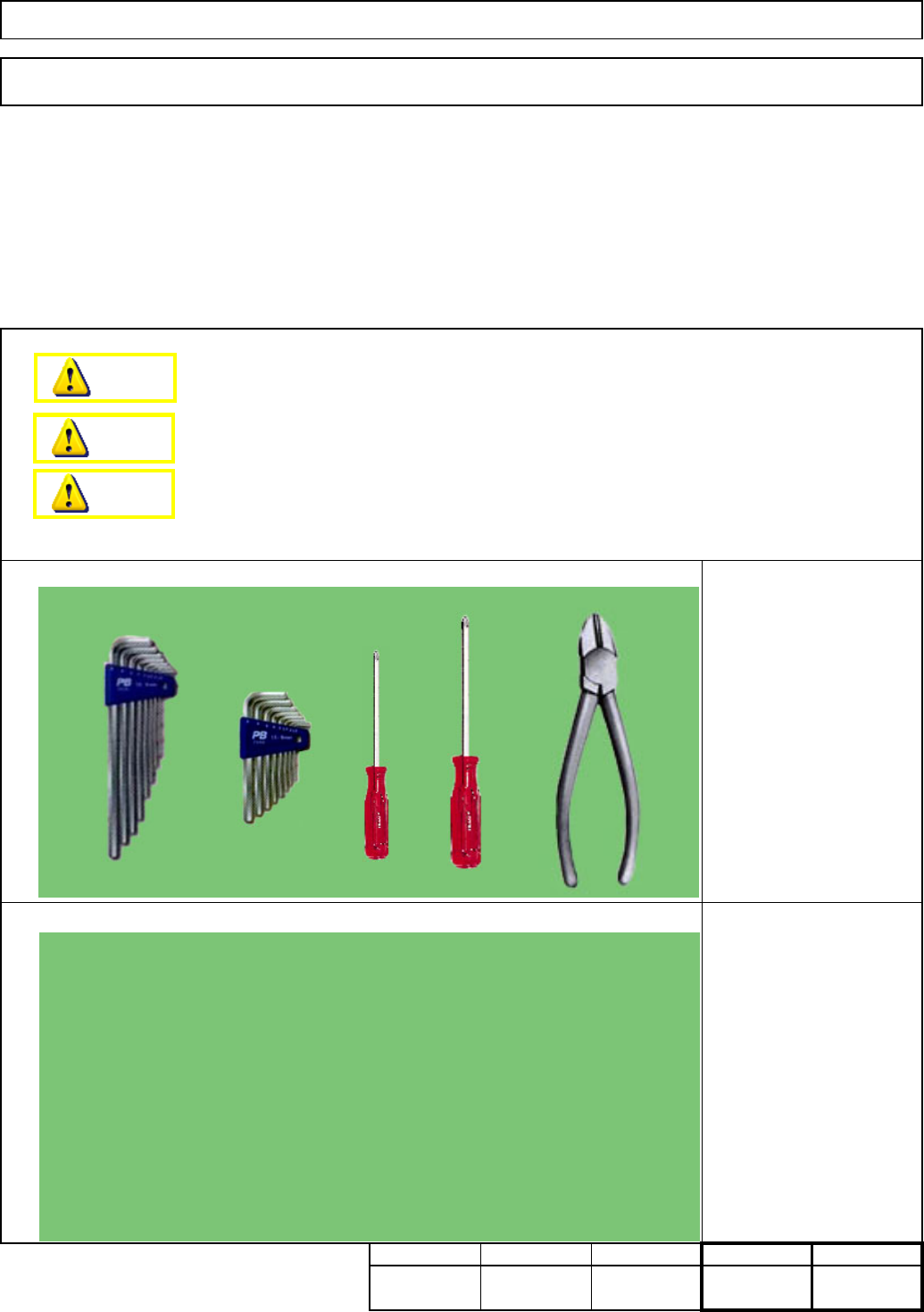
Tool
Jig
Removal/Disassembly
min.
Phillips screwdriver #1
Phillips screwdriver #2
Allen key 3 mm
Allen key 4 mm
Nipper
Teaching
min.
7-1-17 Shuttle Tray Cable and Air Tube Layout
Shuttle TrayTray
This section describes the procedures for securing the shuttle tray cables and the air tube.
Total time Part weight
None
120
180
min
.
Kg
60 min.
Dange
r
Warning
Caution
EJM8A-E-SMA070117-A01-00 Page 7-1-17-1
Remove the side covers from the feeder
section.
(
AR and BR sta
g
es
)
Tray
4
2
1
Item
Turn off the power and air supply.
Remarks
Remove all feeder change carts.
3
Shuttle Tray
Remove all lower chutes.
Allen key 4 mm
M5 x 12 mm 4 pcs x 4
Thick washer 4 pcs x 4
1
2
Left chute
installing
section
Right chute
installing section
EJM8A-E-SMA070117-A01-00 Page 7-1-17-2
Remove the machine side covers.
(
Both sides
)
Philli
p
s screwdriver #2
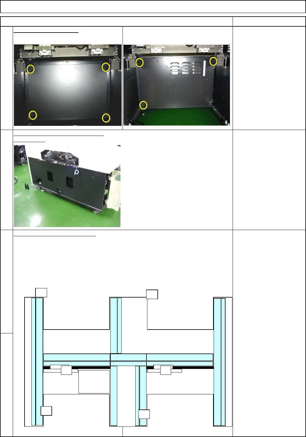
Note: Basic rule for cabling
. Put the power cable into the thinner duct.
. Put the signal cable into the thick duct.
. When the two cables cross each other, put the power cable under the signal cabl
e
Remove the box covers.
6
5
8
Remove the cap from the duct.
Remarks
Tray Shuttle Tray
Phillips screwdriver #2
Button head screw 6mm
15 pcs.
(3 pcs on AF)
7
Item
AF
A4A4
POWER
UNIT#1
POWER
UNIT#2
CPU BOX
AR
BF
BR
EJM8A-E-SMA070117-A01-00 Page 7-1-17-3