CM602all_EJM8AESM_Service Manual.pdf - 第978页
(1) Standard Cable Connectors N2 to N5 are not used. (2) The standard connector TRYS1 should be secured near RY.SA with a cable tie. (3) Standard Cable Connectors N1 to N9 are not used. (4) The standard connector TRYS1 s…
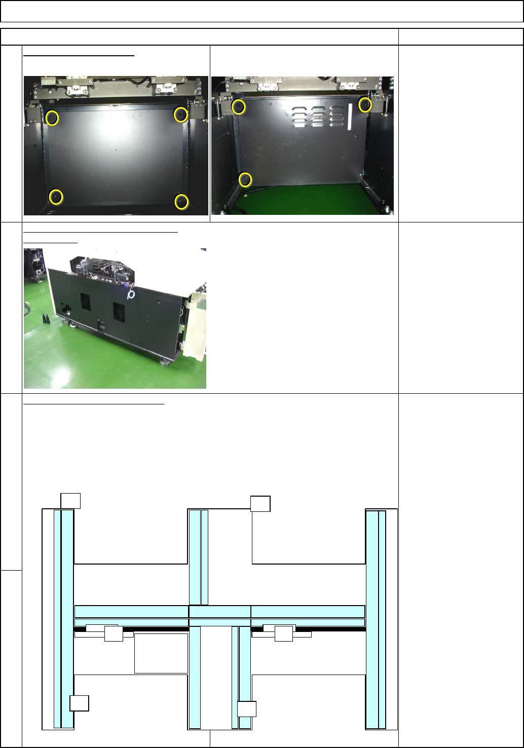
Remove the machine side covers.
(
Both sides
)
Philli
p
s screwdriver #2
Note: Basic rule for cabling
. Put the power cable into the thinner duct.
. Put the signal cable into the thick duct.
. When the two cables cross each other, put the power cable under the signal cabl
e
Remove the box covers.
6
5
8
Remove the cap from the duct.
Remarks
Tray Shuttle Tray
Phillips screwdriver #2
Button head screw 6mm
15 pcs.
(3 pcs on AF)
7
Item
AF
A4A4
POWER
UNIT#1
POWER
UNIT#2
CPU BOX
AR
BF
BR
EJM8A-E-SMA070117-A01-00 Page 7-1-17-3
(1) Standard Cable Connectors N2 to N5 are not used.
(2) The standard connector TRYS1 should be secured near RY.SA with a cable tie.
(3) Standard Cable Connectors N1 to N9 are not used.
(4) The standard connector TRYS1 should be secured near TRY.SB with a cable tie.
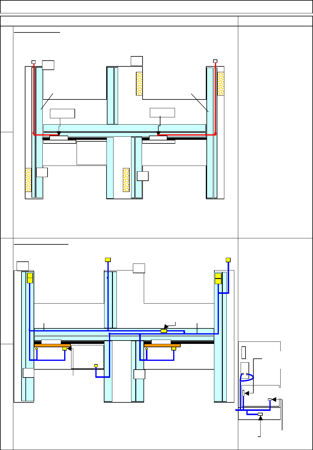
AC Cable Layout
11
10
12
9
91030:
A stage tray signal cable
91040:
B stage tray signal cable
Signal Cable Layout
Item Remarks
Shuttle Tray
91010:
TYR.P1 to TYR.R1
91020:
TYR.P2 to TYR.R2
Tray
AF
TYR.P2
POWER
UNIT#1
POWER
UNIT#2
CPU BOX
AR
BF
BR
TYR.P1
TYR.R1
TYR.R2
9102091010
AF
POWER
UNIT#1
POWER
UNIT#2
CPU BOX
AR
BF
BR
RF2RF2 TRY.SB
N1-N9
TRY.SA
N2-N5
NF0FCX
CN13-NJ
STCV11 STCV21
STHD2
STHD-S
STHD1
STHD-S
ITRY-P/R
91030
91040
Connection of Power Unit
RF1
RF2
NF2ACX
TRY EP
Change to a
short connector.
Change to the
standard cable.
EJM8A-E-SMA070117-A01-00 Page 7-1-17-4
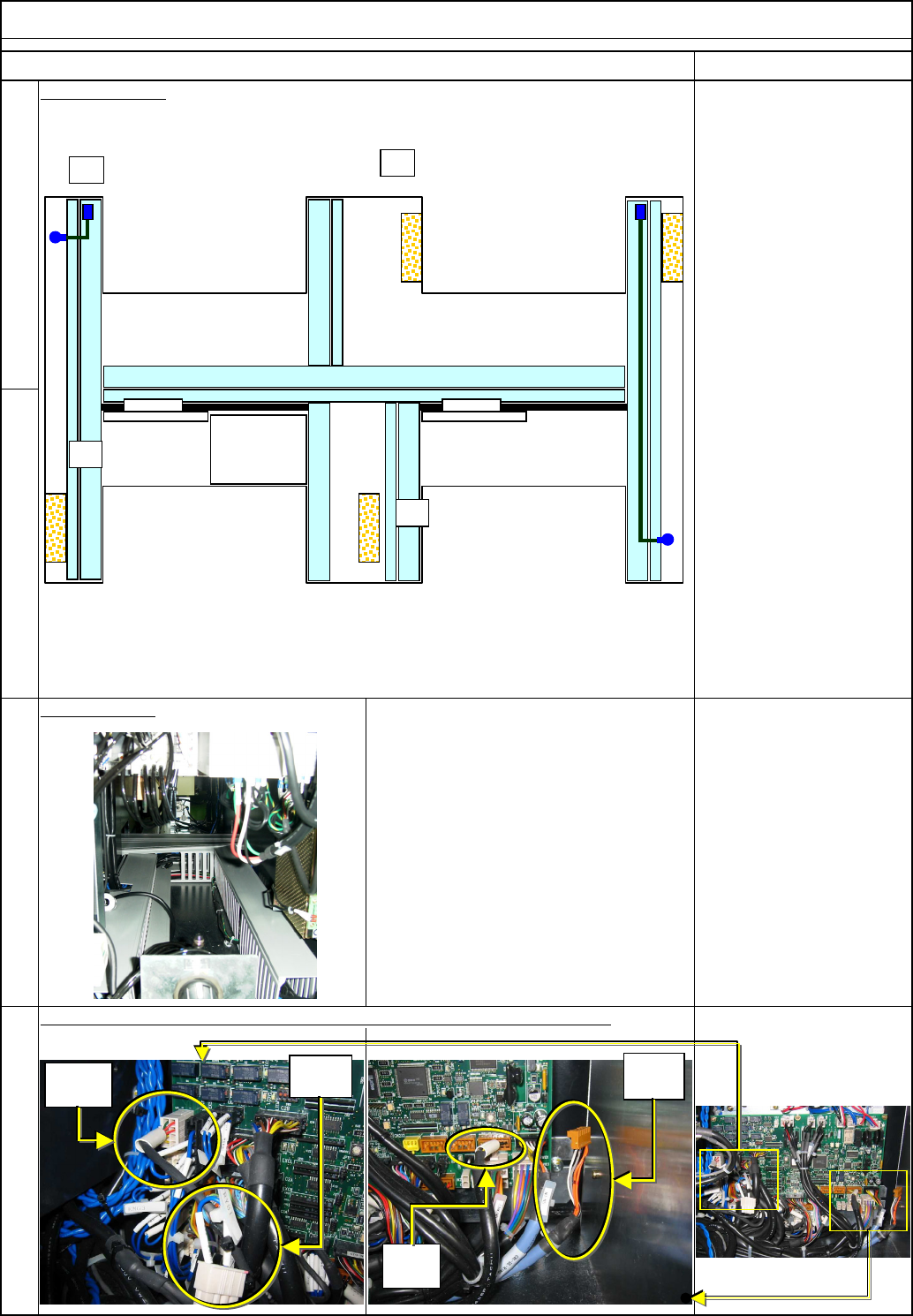
Nipper
Replace the current cable with the standard cable.(2 pcs. for each stage)
Tray Shuttle Tray
14
Item
13
Air Tube Layout
Remarks
15
16
Duct example:
TRY.S
A
Non-
used
Non-
used
N2-N5
N1-N9
POWER
UNIT#1
POWER
UNIT#2
CPU BOX
AR
BF
BR
AF
EJM8A-E-SMA070117-A01-00 Page 7-1-17-5