CM602all_EJM8AESM_Service Manual.pdf - 第98页
Phillips screwdriver screw 4 pcs. [Tool] Tester Precision screwdriver [Specifications] 5.05_0 to +0.03 V [Tool] Tester Precision screwdriver [Specifications] 12.00±0.1 V [Tool] Tester Precision screwdriver [Specification…
Installation
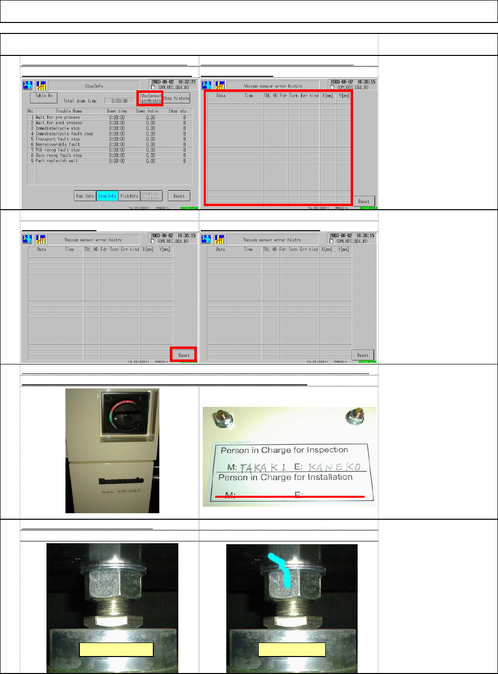
Select (1) "Vacuum sensor error history. are displayed. (2
)
109
Reset the vacuum sensor error record
s
Machine Installation
Remark
Press (3) "Reset.
"
Item
The errors that have occurred so fa
r
The error records disappear
111
112
110
* Grease is applied to the
nut. Remove excess
grease. Put a mark on the
nut.
Even though a magic
marker is used, it may not
work on a grease section.
Confirm a mark on the lock nut
[Person in charge]
Two lines for persons in
charge:
Upper line:
Persons in charge of
shipping
Lower line:
Persons in charge of
installation
Sign the inspection/installation label as shown below: (M for machine, E for electricity)
The label is placed inside the cover under the electric source sectio
(1)
(2)
Before marking After marking
(3)
EJM8A-E-SMA020103-A01-00 Page 2-1-3-29
Phillips screwdriver screw
4 pcs.
[Tool]
Tester
Precision screwdriver
[Specifications]
5.05_0 to +0.03
V
[Tool]
Tester
Precision screwdriver
[Specifications]
12.00±0.1
V
[Tool]
Tester
Precision screwdriver
[Specifications]
24.00 to 24.30
V
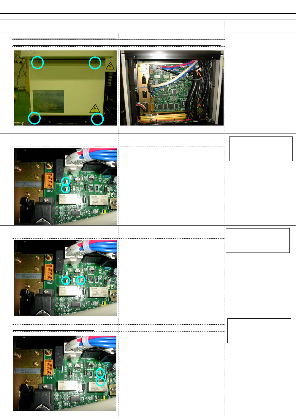
Check it with TP5V and TGGNG
Check it with TP24V and TP24G
116
115
Check it with TP12V and TGGNG
113
ST40T Inspection Voltage Measureme
n
Remove the cover from the control box cover, which is placed under the shuttle tray.
114
Installation Machine Installation
Item Remark
TP5V red
TGGND black
Tester DC 20V range
TP12V red
TGGND black
Tester DC 20V range
TP24V red
TP24G black
Tester DC 20V range
EJM8A-E-SMA020103-A01-00 Page 2-1-3-30
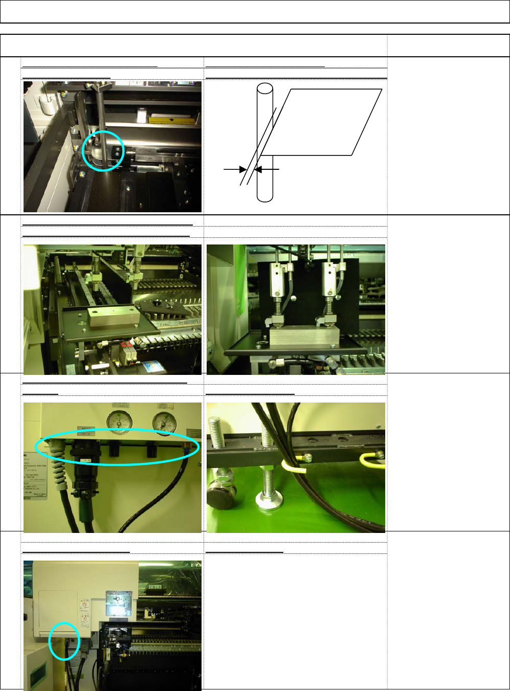
within 0.1 to 0.2mm
(Teaching on the shuttle and tray side
s
117
Check the pickup and delivery position
s
Cable and Tube Position Cables and Tube
s
Check the ST40T for operation
118
Basically check only
120
119
[Care when the shuttle tray
is set]
Set the shuttle tray delivery
jig on the transfer conveyor.
Adjust the installation angle
of the shuttle tray so that
the two tray nozzles are
placed in the jig.
Cable and Tube Position on the shuttl
e
tray sid
e
How to secure them
:
Machine Installation
Item Remark
Installation
* Adjust it with the magazine cover stopp
e
[If adjustment is necessary:
[Specifications]
With the shutter closed, the
gap from the magazine
stopper to the palette
should be 0.1 to 0.2 mm.
Palette
EJM8A-E-SMA020103-A01-00 Page 2-1-3-31