CM602all_EJM8AESM_Service Manual.pdf - 第997页
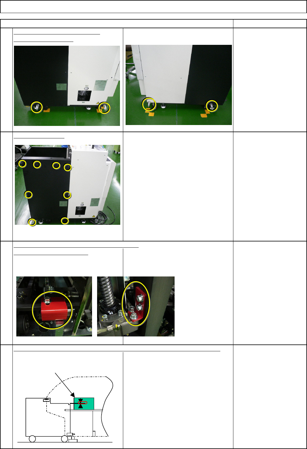
4 Remark 2 1 3 Connect the tray to the machine. Remove the cover. Left: TP-axis, Right: TL-axis Eye bolt x 4 pcs. Remove the eye bolts. Item Tray Direct Tray Insert the main body of the tray into the machine. Adjust the …
40
45
Min.Min.
kgs.
Tray Direct Tray
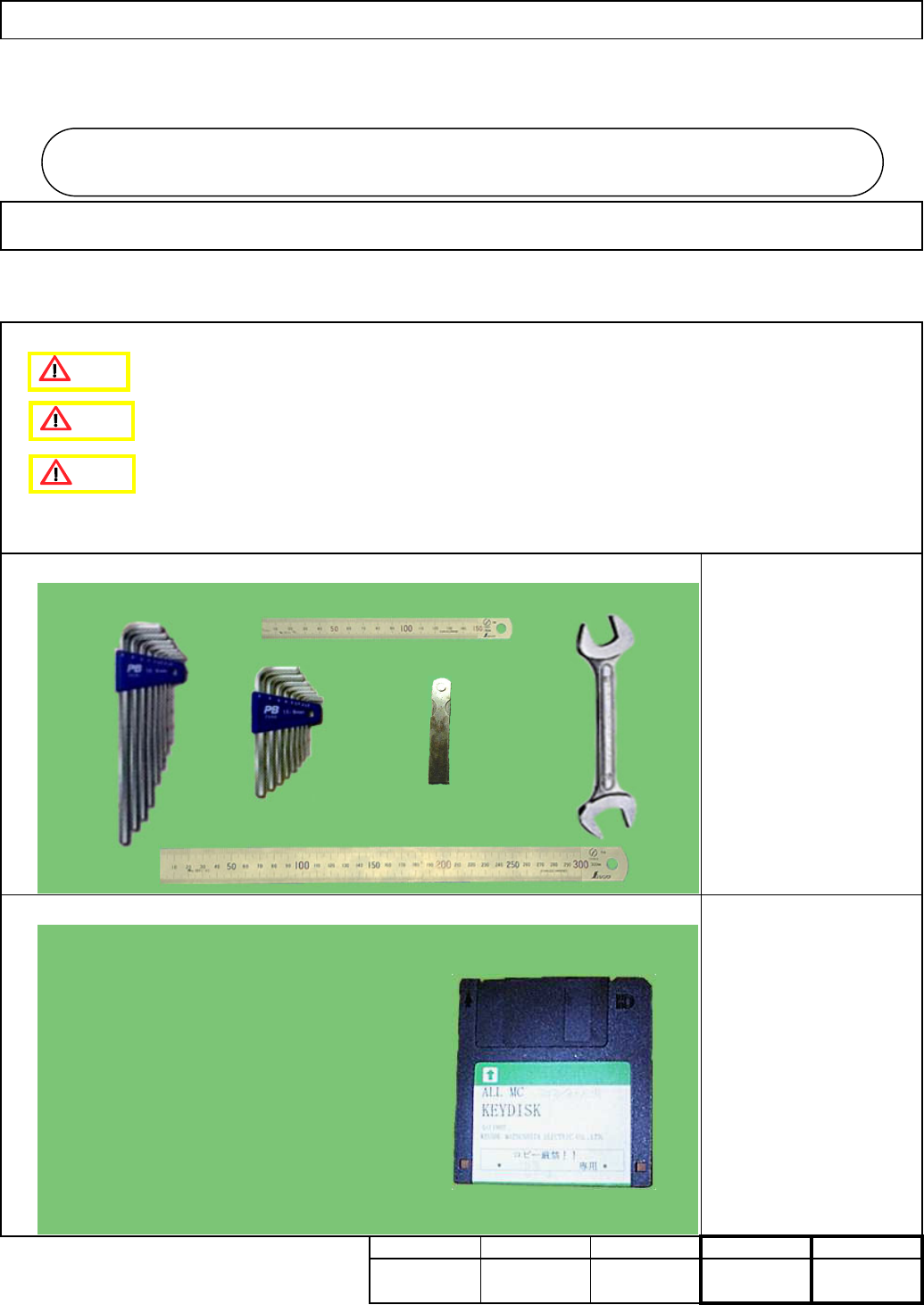
Key disk
Nozzle 1003
7-2-1 Direct Tray Installation
Assembly/AdjustmentRemoval/Disassembly
• This section describes the procedures for installing the direct tray.
Total Part Weight
Tool
Jig
Allen key 4 mm
Allen key 5 mm
Allen key 6 mm
Wrench 300mm
Ruler 150 mm
Ruler 300 mm
Teaching
5
Min. Min.
Direct Tra
y
I Since this adjustment requires releasing the safety cover switch, only those who are
authorized to release it based on the Document "Key Switch/Key Disk Receipt
Confirmation and Safety Precautions" are permitted to perform this adjustment.
II Since this adjustment requires parameter changes using the key disk, only those who
are authorized to use the key disk based on the "Key Switch/Key Disk Receipt
Confirmation and Safety Precautions" are permitted to perform this adjustment.
7-2
Caution
Danger
Warning
EJM8A-E-SMA070201-A01-00
Page 7-2-1-1
4
Remark
2
1
3
Connect the tray to the machine.
Remove the cover.
Left: TP-axis, Right: TL-axis
Eye bolt x 4 pcs.
Remove the eye bolts.
Item
Tray Direct Tray
Insert the main body of the tray into the machine. Adjust the height of the tray.
Remove the holding brackets. Install the cover.
Before installing the DT50S, adjust
the height of the rear side of the
DT50S, using the height of the 6-series-
holding feeder cover as reference.
⇒ within 0/-1mm
①
6-series-holding
feeder cover
EJM8A-E-SMA070201-A01-00
Page 7-2-1-2
Check the position of the holding bolt.
⇒ within
+/-0.3mm/m
⑤ Connect the tray to the machine with
the holding bolts. (Fix the two positions
with the manually-turning handle.)
Right of the machine: Fix one position
⑤ Connect the tray to the machine with
the holding bolts. (Fix the two positions
with the manually-turning handle.)
Left of the machine: Fix one position
After inserting the DT50S, re-check
the level. ⇒ within 0.3mm/m
After inserting the DT50S, check the
height of the DT50S by checking the
height difference between the 6-series
holding feeder cover and the tray.
⇒ A=within 0/-1mm
Connect the tray to the machine with
the holding bolts. (Fix the two positions
with the manually-turning handle.)
Tray Direct Tray
Checking the levels mounted in the
machine, level the tray.
Level the tray by adjusting the caster.
Wrench 300 mm
Check the position of the holding bolt.
of the tray.
Re-check the levelness and the height
6
7
8
5
Item
* Tighten the nut for
the caster "a" only.
Remark
②
a
③
Holding bolts
⑤
⑤
④
6-series-holding
feeder cover
6-series-holding
feeder cover
EJM8A-E-SMA070201-A01-00
Page 7-2-1-3