CM602all_EJM8AESM_Service Manual.pdf - 第998页
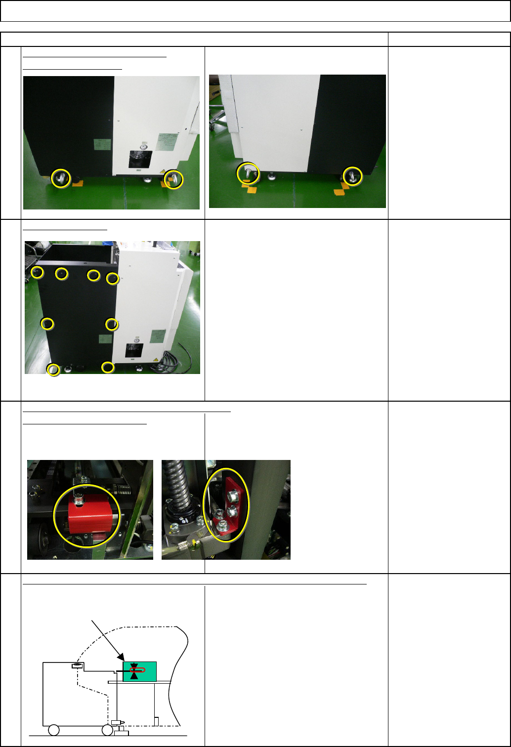
Check the position of the holding bolt. ⇒ within +/-0.3mm/m ⑤ Connect the tray to the machine with the holding bolts. (Fix the two positions with the manually-turning handle.) Right of the machine: Fix one position ⑤ Con…
4
Remark
2
1
3
Connect the tray to the machine.
Remove the cover.
Left: TP-axis, Right: TL-axis
Eye bolt x 4 pcs.
Remove the eye bolts.
Item
Tray Direct Tray
Insert the main body of the tray into the machine. Adjust the height of the tray.
Remove the holding brackets. Install the cover.
Before installing the DT50S, adjust
the height of the rear side of the
DT50S, using the height of the 6-series-
holding feeder cover as reference.
⇒ within 0/-1mm
①
6-series-holding
feeder cover
EJM8A-E-SMA070201-A01-00
Page 7-2-1-2
Check the position of the holding bolt.
⇒ within
+/-0.3mm/m
⑤ Connect the tray to the machine with
the holding bolts. (Fix the two positions
with the manually-turning handle.)
Right of the machine: Fix one position
⑤ Connect the tray to the machine with
the holding bolts. (Fix the two positions
with the manually-turning handle.)
Left of the machine: Fix one position
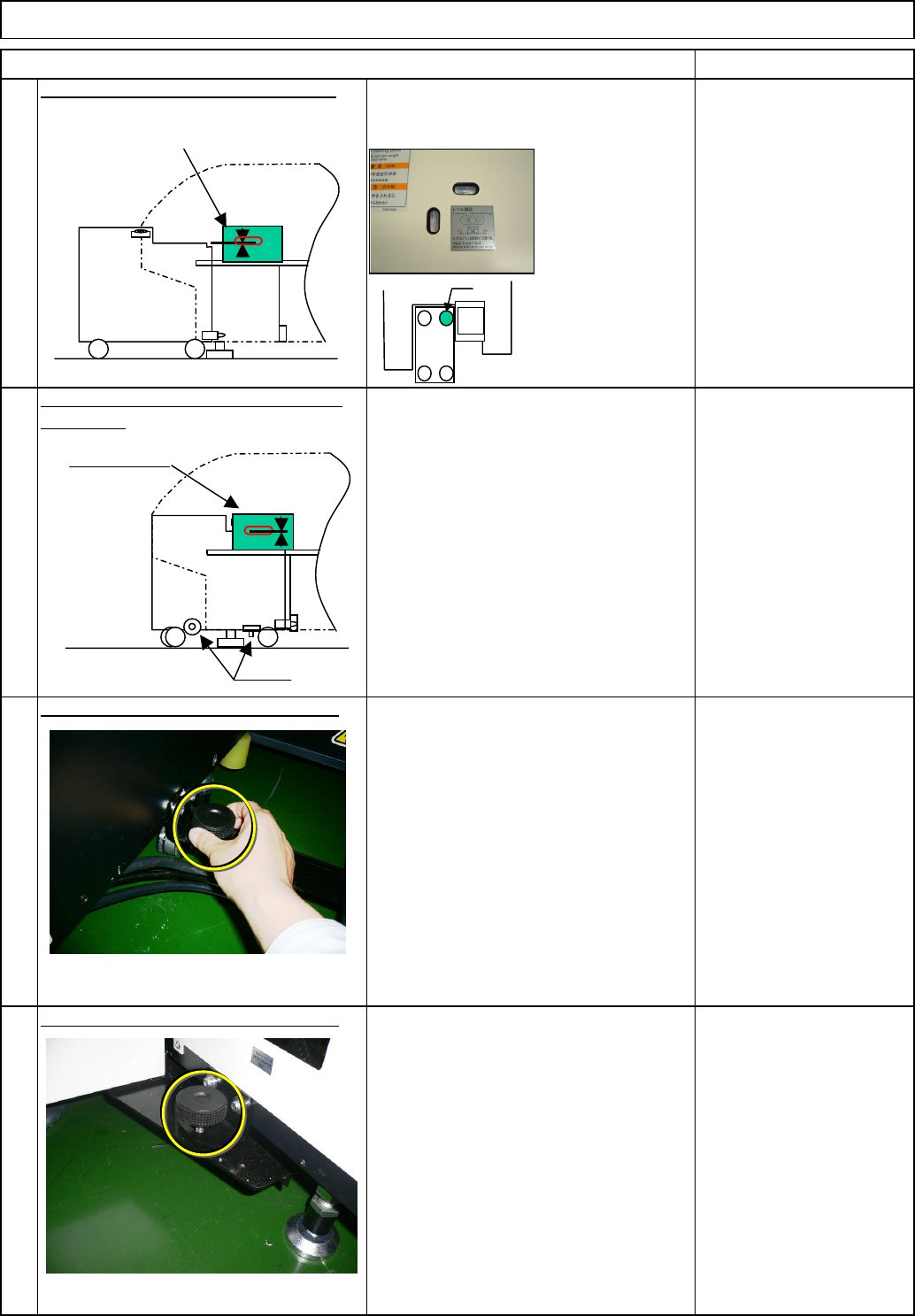
After inserting the DT50S, re-check
the level. ⇒ within 0.3mm/m
After inserting the DT50S, check the
height of the DT50S by checking the
height difference between the 6-series
holding feeder cover and the tray.
⇒ A=within 0/-1mm
Connect the tray to the machine with
the holding bolts. (Fix the two positions
with the manually-turning handle.)
Tray Direct Tray
Checking the levels mounted in the
machine, level the tray.
Level the tray by adjusting the caster.
Wrench 300 mm
Check the position of the holding bolt.
of the tray.
Re-check the levelness and the height
6
7
8
5
Item
* Tighten the nut for
the caster "a" only.
Remark
②
a
③
Holding bolts
⑤
⑤
④
6-series-holding
feeder cover
6-series-holding
feeder cover
EJM8A-E-SMA070201-A01-00
Page 7-2-1-3
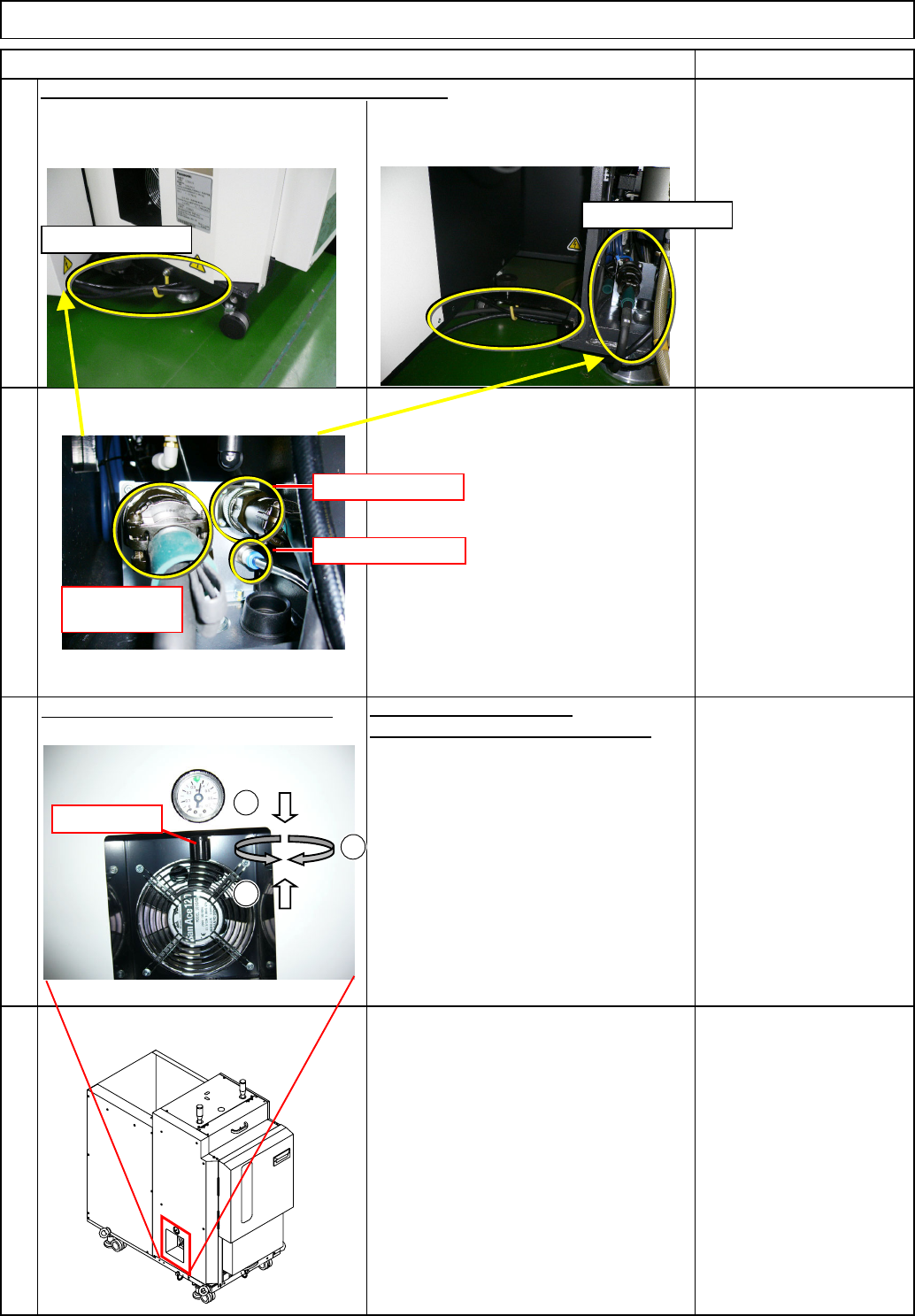
Connect the signal and power cables and the tubes.
AR: Put the cables and the tubes on the
front left, and secure them as shown
below.
BR: Put the cables and the tubes on the
rear right, and secure them as shown
below.
Specified air pressures:
0.3 MPa to 0.35 Mpa
2. If out of range, adjust the pressure by
turning the regulator.
1. Check the operating air pressure
.
Unlock
Tray Direct Tray
10
11
Check the operating air pressure.
12
Adjust the pressure.
Loc
k
Turn on the power switch.
Item Remark
9
Power cable
Communication
cable
Air tube
1
2
3
Regulator
Where to connect
Where to connect
EJM8A-E-SMA070201-A01-00
Page 7-2-1-4