User Manual - SIPLACE Glue Feedeer - 第21页
2 General 2.2 Module Description User Manual SIPLACE Glue Feeder 05/2020 21 Optimization of glue dot quality If you increase the plunger setting >0.6mm (>60N ), this also increases the spring pre-tension in the j…
2 General
2.2 Module Description
20 User Manual SIPLACE Glue Feeder 05/2020
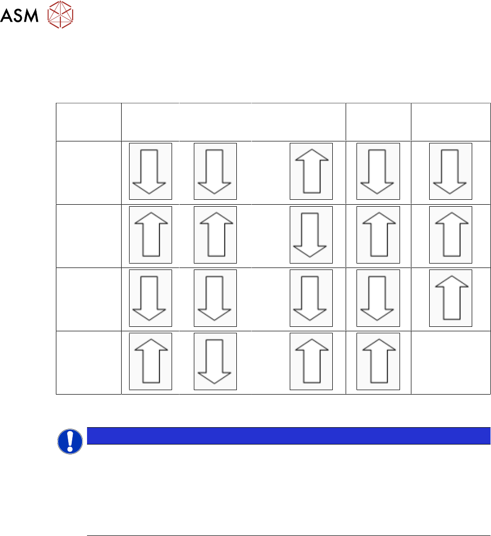
2.2.8 Settings Table
The following table should help you to find the optimum Glue Feeder setting for your requirements.
Die to the various different adhesives this table can not be seen as exhaustive and is only intended
as an overview data based on experience.
Pressure
at
jet valve
Pressure at
cartridge
Plunger setting
in mm
Temperat-
ure
(heating)
Diameter
of nozzle
Smaller
glue dots
>0.6
Larger
glue dots
<0.6
Avoid
satellite form-
ation
<0.6
Avoid
glue residues
on the nozzle
>0.6
--
2.2.9 Setting the Jet Plunger
NOTICE
Increased wear when pressure is higher
The jet plunger is factory set to 60N (corresponds to 0.6mm plunger setting). This setting
allows the SIPLACE Glue Feeder to process common epoxy resin-based SMD adhesives
reliably and in high quality.
After changing this setting, you may need to adjust the characteristics at the station.
Please note that higher settings (>60N) will lead to increased wear of the jet plunger and
particularly to the dispenser nozzle.
We recommend that you check the plunger setting in the following cases:
●
General check of factory setting to 0.6 mm
●
Same setting when using multiple Glue Feeders at your site
●
Optimization of glue dot quality
General check of factory setting to 0.6 mm
If the quality of the glue dots should deteriorate, despite regular maintenance, and if this can not be
remedied with the temperature and pressure settings, the plunger setting can be checked using the
plunger measuring system "Measuring system - plunger adjustment", item no. 03126592-01.
Checking and setting of the jet plunger is described in the service manual for the Glue Feeder item
no. 00197278-xx, chapter "Replacing Spare Parts", in the section about "Jet Valve P-Dot".
Same setting when using multiple Glue Feeders at one site
To avoid differences in the size and quality of the glue dots between the individual Glue Feeders,
the Glue Feeders can be checked with the plunger measurement system and adjusted, if neces-
sary.

2 General
2.2 Module Description
User Manual SIPLACE Glue Feeder 05/2020 21
Optimization of glue dot quality
If you increase the plunger setting >0.6mm (>60N ), this also increases the spring pre-tension in
the jet valve. The consequence of this is that the glue dot is dispensed with more power. This can
lead to improvements when using adhesives which have a high viscosity.
If you increase the plunger setting, less adhesive flows into the dispenser nozzle between the indi-
vidual "shots". This means that, although the number of shots remains the same, a lower volume of
adhesive is applied to the component. Depending on the viscosity of the glue and the type of
component surface, this might cause the glue dot to have a wider diameter. The cause for this is
that the glue is dispensed with greater power and therefore at a higher speed. This change must be
taken into account when setting the characteristic line, in relation to the glue dot check by the Vis-
ion system.
Furthermore, a higher plunger setting will lead to flatter glue dots, if the number of shots remains
the same. Check whether the contact between the glue dot and the board is present and increase
the number of shots where necessary.
We recommend that the plunger setting only be increased as far as really needed. Changes to the
plunger setting are only advisable if you are using other glues than those recommended by us. Ob-
serve in particular the information about increased wear of the jet plunger and at the dispenser
nozzle.
If you reduce the plunger setting <0.6mm (<60N), the characteristics will change in the opposite
direction to that described above. To make sure that the shape of your glue dot is acceptable, you
should not set the jet plunger to <0.2mm (<20N).
The jet plunger setting range is between 0.2mm and 1.5mm (20N to 150N).

2 General
2.3 Glue Dot Inspection and Teaching with SIPLACE Vision
22 User Manual SIPLACE Glue Feeder 05/2020
2.2.10 EU Declaration of Conformity
The product/device described conforms to the regulations and standards listed in the EU Decla-
ration of Conformity provided.
Manufacturer:
ASM Assembly Systems GmbH & Co. KG
Rupert-Mayer-Str. 44
D-81379 Munich
2.3 Glue Dot Inspection and Teaching with SIPLACE Vision
During the glue dot inspection, the glue dot is dispensed and then visually checked using a cam-
era. In order for a glue dot to be recognized and evaluated by SIPLACE Vision, a reference image
of the component is made just before the glue is applied to the component. This image is then
compared to the current image in which the glue has already been applied.
During a measurement job with glue dot inspection, the following is checked for each glue dot:
●
Is the glue dot present?
●
Is the size of the glue dot within the prescribed tolerance i.e. is the measured diameter of the
glue dot between the minimum and maximum circular area in the model?
●
is the glue dot within the prescribed target area? A rectangular target area can be defined in
the model. The inspection then checks whether the glue dot is completely within this target
area. If the glue dot touches the edge of the target area, an error will be reported.
Separate illumination can be set for the glue dot inspection as an option.
The following glue dot parameters can be changed in the CS Editor, with the station software:
●
Inspection (yes/no)
●
Tolerance for diameter of glue dot
●
Coordination of target area (size)