User Manual - SIPLACE Glue Feedeer - 第35页
4 Operation 4.1 Settings in SIPLACE Pro 10.1 and Higher User Manual SIPLACE Glue Feeder 05/2020 35 ► In the tree view, click on the component shape which you want to edit. The selected component shape will be shown.
4 Operation
4.1 Settings in SIPLACE Pro 10.1 and Higher
34 User Manual SIPLACE Glue Feeder 05/2020
4.1.1 Defining a Component Shape Glue Dot Model
This is where you define the position and the size of one or more glue dots which you want to use
to fix the component to the board.
Depending on the size of the component, you will either need one or more glue dots for the fixture
to the board. The position of the glue dots can be chosen wherever required, provided the following
instructions are observed:
The correct position and size of the glue dots can also be optionally checked by activating the Vis-
ion Inspection function.
NOTICE
Placement head contamination
The glue dot and the target rectangle must be within the component shape (without leads).
If not, the dispense procedure could contaminate the placement head with glue.
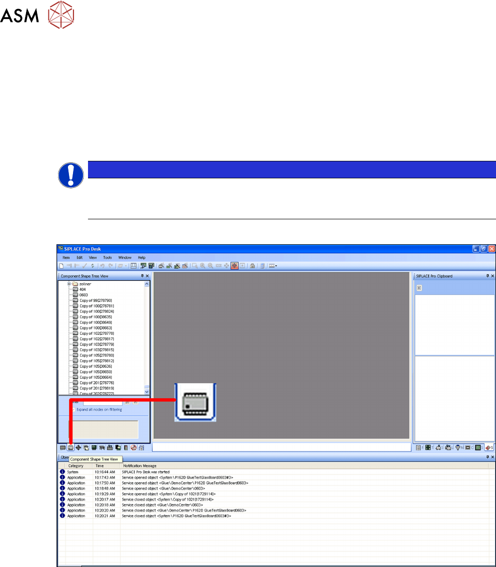
Procedure
► Switch over to the main window.
► Click on the Component shape – tree view icon.
The component shape tree view will be shown.
4 Operation
4.1 Settings in SIPLACE Pro 10.1 and Higher
User Manual SIPLACE Glue Feeder 05/2020 35
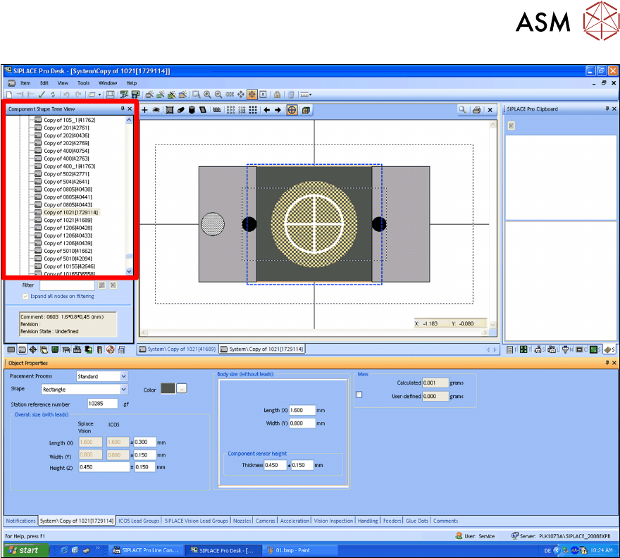
► In the tree view, click on the component shape which you want to edit.
The selected component shape will be shown.
4 Operation
4.1 Settings in SIPLACE Pro 10.1 and Higher
36 User Manual SIPLACE Glue Feeder 05/2020
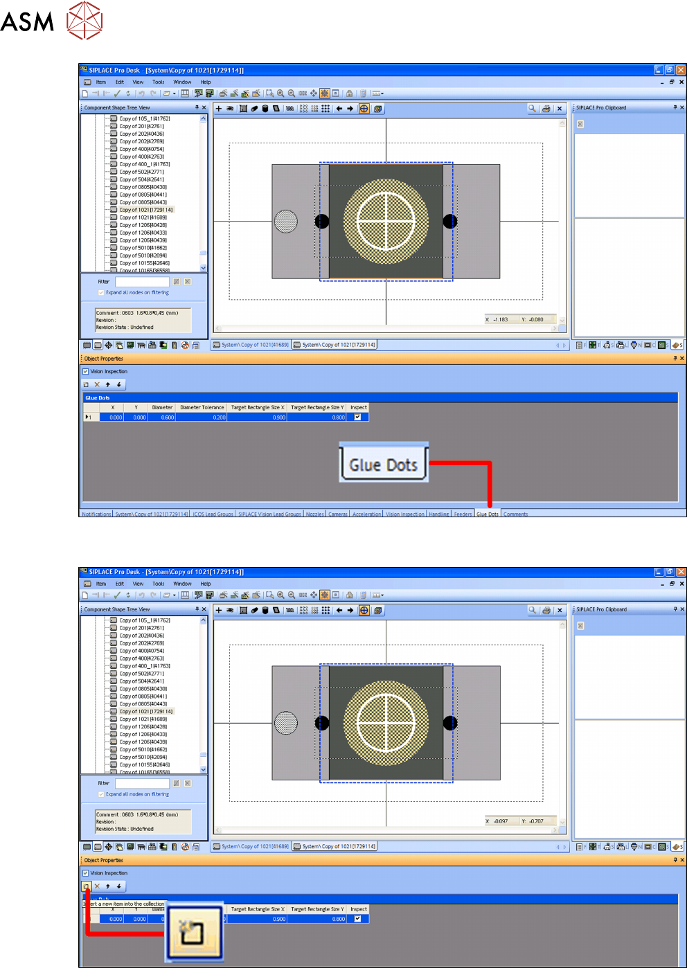
► In the footer click on the Glue Dots tab.
The object properties for the component shape will be shown.
► Click on the icon Insert a new item into the collection.
This shows a new line, in which you can define a glue dot and its corresponding information.
► Define the required glue dot.