User Manual - SIPLACE Glue Feedeer - 第38页
4 Operation 4.1 Settings in SIPLACE Pro 10.1 and Higher 38 User Manual SIPLACE Glue Feeder 05/2020 4.1.2 Enabling/Disabling Gluing in the Component Object Properties This is a global setting which specifies whether the c…
4 Operation
4.1 Settings in SIPLACE Pro 10.1 and Higher
User Manual SIPLACE Glue Feeder 05/2020 37
► If you want to define more glue dots, click again on the Insert a new item into the collection
icon and enter the required values in the lines provided.
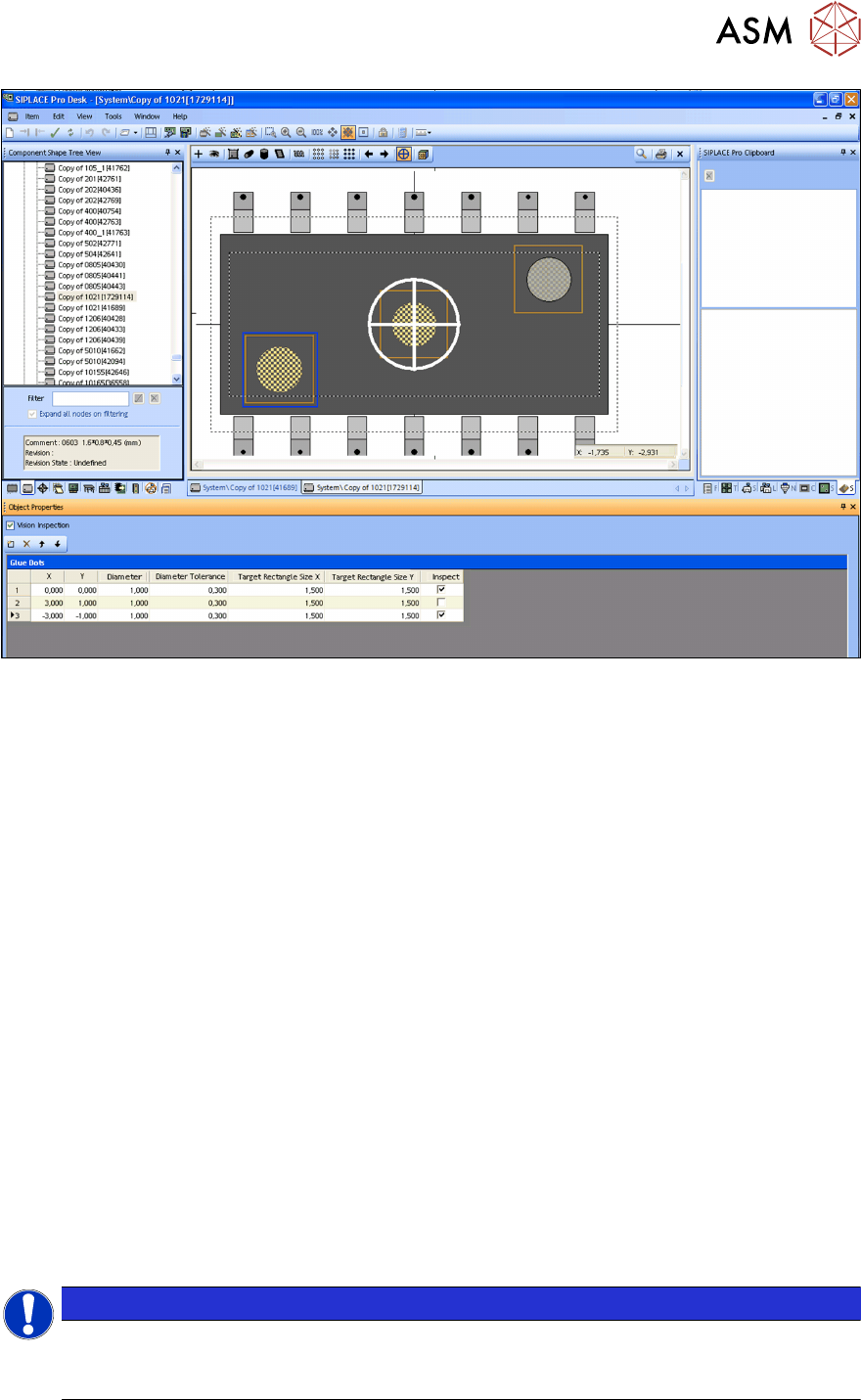
Define the individual glue dot parameters in the lines of the tables shown below (diagram). On the
screen, the yellow line shows the target area you have defined and the blue line the specified toler-
ance range.
Vision inspection
► Define whether you want a Vision inspection to be performed as a default for this component
shape. If this option is disabled, any other settings for inspection of this component shape will
be ignored.
X/Y
► Use these coordinates to define the position of the glue dot on the component shape.
Diameter
► Define the diameter of the glue dot in mm. The glue dot is realized either with one or more in-
dividual dots (droplets), depending on the specified diameter.
Diameter tolerance
► Define the tolerated deviation from the specified diameter in mm for the Vision inspection.
Target rectangle X / Y
► Define the area in which the glue dot is to be expected for the Vision inspection.
Inspection
► Define whether this glue dot is to be checked by the Vision inspection or not.
The Vision inspection will only be performed if the superior option Vision Inspection
(top) has
been enabled.
NOTICE
Placement head contamination
The glue dot and the target rectangle must be within the component shape (without leads).
If not, the dispense procedure could contaminate the placement head with glue.
4 Operation
4.1 Settings in SIPLACE Pro 10.1 and Higher
38 User Manual SIPLACE Glue Feeder 05/2020
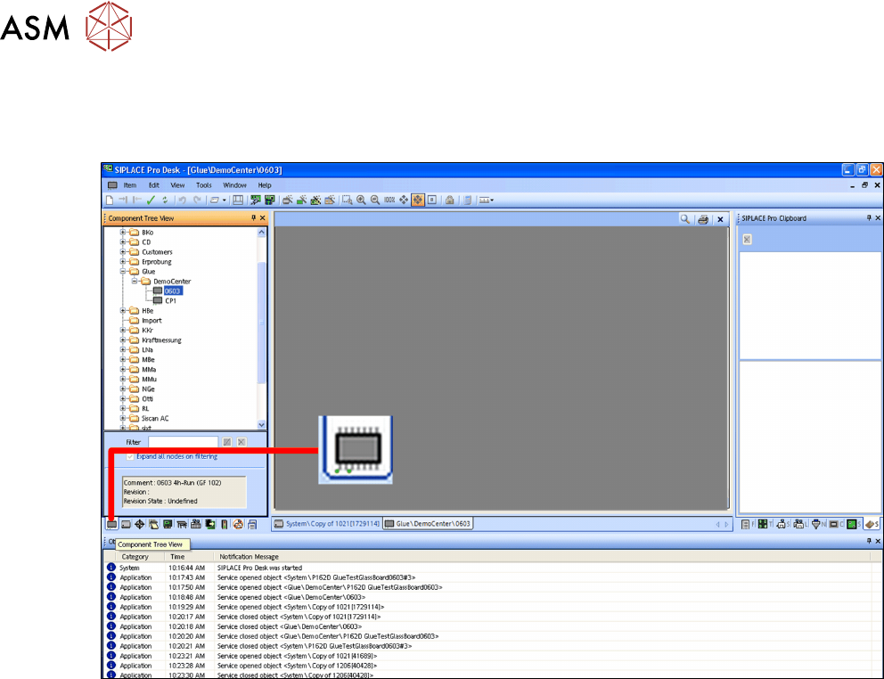
4.1.2 Enabling/Disabling Gluing in the Component Object Properties
This is a global setting which specifies whether the component may be glued during placement or
not.
► Switch over to the main window.
► Click on the Components – tree view icon.
The component tree view will be shown.
► Select the component to be processed.
4 Operation
4.1 Settings in SIPLACE Pro 10.1 and Higher
User Manual SIPLACE Glue Feeder 05/2020 39
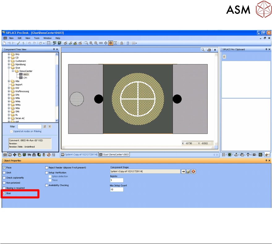
The object properties for the selected component will be shown.
The diagram shows the option Glue marked.
Gluing
If this option is enabled, the selected component will be released for gluing during the placement
process. You can then define in the placement list whether this component is actually to be glued
or not.