User Manual - SIPLACE Glue Feedeer - 第63页
4 Operation 4.3 Manual Settings User Manual SIPLACE Glue Feeder 05/2020 63 4.3 Manual Settings 4.3.1 Setting the Pressure Reducer 1. Pressure reducer for the pressure at jet valve of dispenser nozzle 2. Pressure reducer …
4 Operation
4.2 Individual Functions in Stations Software 706.1 and Higher
62 User Manual SIPLACE Glue Feeder 05/2020
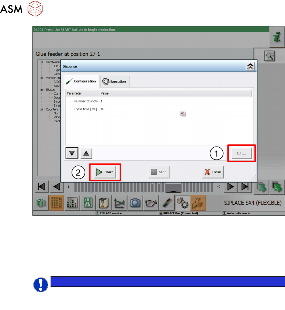
► This dialog allows you to change the number of glue dots and the cycle time (in milliseconds).
Select the parameters to be changed and click on Edit
. (1)
Set the value as required in the dialog shown and then click on Accept.
► To test the glue, click on Start. (2)
The glue will be applied to the paper tape.
► Take the safety cover off the Glue Feeder and check the test result.
You can repeat this procedure as often as you need.
NOTICE
Removing the safety cover
Once the tests have been completed, remove the safety cover from the Glue Feeder and
close the machine cover.
4 Operation
4.3 Manual Settings
User Manual SIPLACE Glue Feeder 05/2020 63
4.3 Manual Settings
4.3.1 Setting the Pressure Reducer
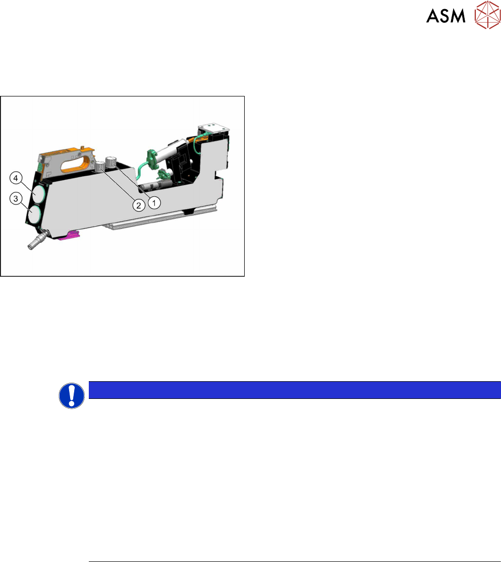
1. Pressure reducer for the pressure at jet valve of
dispenser nozzle
2. Pressure reducer for the pressure at the cartridge
3. Manometer for the pressure at the cartridge
4. Manometer for the pressure at the jet valve of the
dispenser nozzle
The current pressure settings are shown at both manometers.
The pressure at the cartridge and the jet valve may need to be adjusted according to the glue used.
For an overview of the individual values, refer to section 2.2.5
"Overview of Glues" [}16].
► To lower the pressure, turn the valve on the pressure reducer to the left.
► To increase the pressure, turn the valve on the pressure reducer to the right.
This change will be shown on the manometer belonging to the pressure reducer.
NOTICE
Use an external compressed air connection if you need a dispensing pressure > 4.5
bar
If the Glue Feeder is not supplied with compressed air via an external source but from the
compressed air connection of the placement machine, we recommend that the pressure re-
ducer for the pressure at the jet valve is set to max. 4.5bar. A pressure of 2 to max. 4.5bar
is usually sufficient for all common SMT adhesives.
If you want to use special adhesives in your production, which need a higher dispensing
pressure than 4.5 bar, the Glue Feeder should in this case be supplied via an external com-
pressed air connection, separate from the placement machine.
Background: If you set higher dispensing pressures than 4.5, you may experience brief re-
curring pressure drops to 4.5 bar at the compressed air connection of the placement
machine, if there are other compressed air consumers (e.g. the tape cutter) being activated.
This could cause irregular glue droplet sizes to be produced.
4 Operation
4.3 Manual Settings
64 User Manual SIPLACE Glue Feeder 05/2020
4.3.2 Setting the Glue Temperature
The value last set is always saved in the glue feeder.
To edit a setting, proceed as follows:
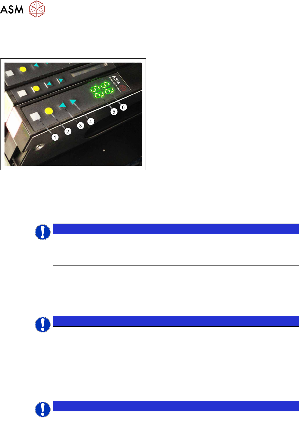
► Press the gray button (1), to access the Setting
the Temperature submenu.
"tE" will be shown in place of the actual temperat-
ure (6)
.
► Use the arrow keys (3, 4) to set the required
nominal temperature. Each press of the key
changes the nominal temperature by one degree.
The back arrow key (3) lowers the value.
The front arrow key (4)
increases the value.
The back display (5) shows the target value which you
are currently setting.
The front display (6)
shows the current temperature of
the glue.
► Press the yellow button (2), to save the set value.
The set temperature is sent to the machine.
4.3.3 Calibrating the temperature regulation
Due to different absolute values, the measuring resistance may vary within the permissible toler-
ances and the values shown on the individual Glue Feeders could deviate (offsets). To ensure that
measurement is more precise and uniform, the calibration of the Glue Feeders determines an indi-
vidual compensation value for each Glue Feeder and stores this.
NOTICE
Calibration recommended
To enable you to use uniform temperature profiles for the various adhesives required for
multiple Glue Feeders in the same production environment, we recommend calibrating the
individual Glue Feeders with the Glue Feeder calibration device (item no. 03214618-xx).
Performing the calibration
ü The Glue Feeder is located on an X FCU or a single slot EDIF (SSE).
ü The feeder module must still be de-energized. This means:
do not fully insert a feeder module into an X-FCU.
The power supply must be switched off on a SSE.
NOTICE
Only connect and disconnect the heating cable when de-energized!
The heating cable may not be connected to or disconnected from the nozzle heating or the
calibration device when energized. Make sure that the Glue Feeder is de-energized before
connecting or disconnecting!
ü When using the calibration device, you need at least the embedded software (eSW) applica-
tion version1.02 at the SIPLACE Glue Feeder.
► Disconnect the heating cable from the nozzle heating.
► Connect the heating cable to the calibration device.
NOTICE
Selecting the correct connection on the calibration unit
The calibration device has 2 connection options: the socket fits an older version of the heat-
ing cable. The plug fits to a newer version of the heating able. (The diagram shows the
newer version of the heating cable.)