User Manual - SIPLACE Glue Feedeer - 第88页
5 Cleaning and Maintenance 5.6 Guide Bushing and Actuator O-Ring 88 User Manual SIPLACE Glue Feeder 05/2020 5.6 Guide Bushing and Actuator O-Ring The tasks described in this section are performed 1x month. It is wise to …
5 Cleaning and Maintenance
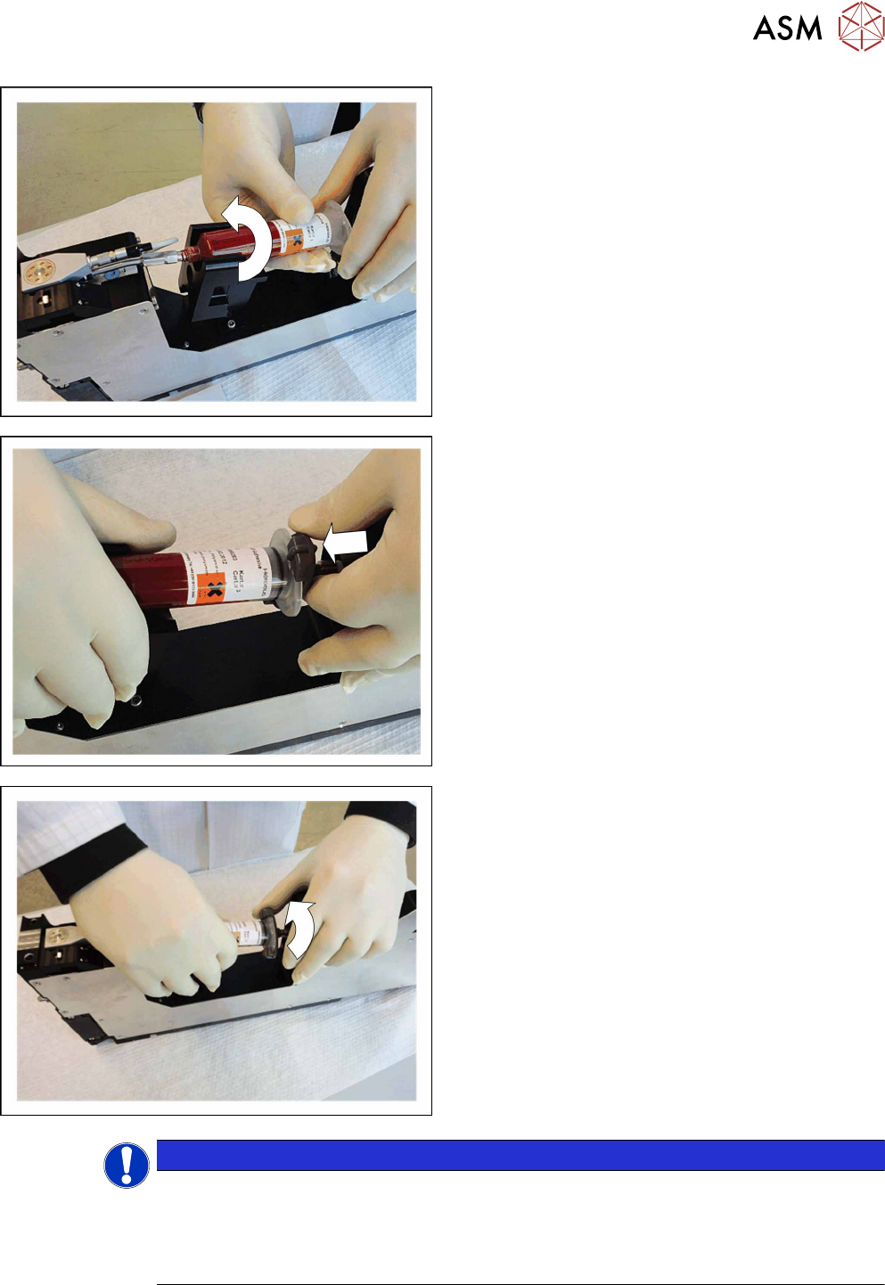
5.5 Replacing the Cartridge
User Manual SIPLACE Glue Feeder 05/2020 87
► Hold the cartridge against the cartridge pipe and
screw it on to the pipe straight.
► Fit the cartridge adapter at the straight points
onto the back of the cartridge and press on as far
as the stop.
► Turn the cartridge adapter clockwise onto the
cartridge, as far as the stop.
► Make sure that the O-ring on the cartridge adap-
ter is completely flush against the inside of the
cartridge and seals it. If not, the required working
pressure will not form.
To make it easier to insert the adapter with the
O‑ring, you can grease the O-ring slightly (Tur-
motemp II/400 CL2).
NOTICE
Predosing
Although you have inserted the cartridge, the Glue Feeder is still not ready for use. You first
need to position the Glue Feeder at the required location and predose the glue unit (cart-
ridge pipe, jet block and dispenser nozzle) i.e. fill it with glue. For a detailed description,
refer to section 3.5
"Predosing the Glue Feeder" [}30].
5 Cleaning and Maintenance
5.6 Guide Bushing and Actuator O-Ring
88 User Manual SIPLACE Glue Feeder 05/2020
5.6 Guide Bushing and Actuator O-Ring
The tasks described in this section are performed 1x month.
It is wise to combine these tasks with cleaning and inspecting the glue unit (see section 5.4 "Clean-
ing and Inspecting the Gluing Unit" [}70]) as this unit has already been taken apart for these tasks.
5.6.1 Removing the Actuator O-Ring and Guide Bushing
► Unscrew and take apart the glue unit (see section 5.4.1 "Dismantling the Gluing Unit" [}70]).
► If necessary, clean the glue unit (see section 5.4.2 "Cleaning the Gluing Unit" [}75]).
► Place the Glue Feeder to one side and pull it up to the edge of the table.
DANGER
Risk of damage
Never exert side forces against the plunger. The valve could be seriously damaged by this.
This would cause the Glue Feeder to malfunction.
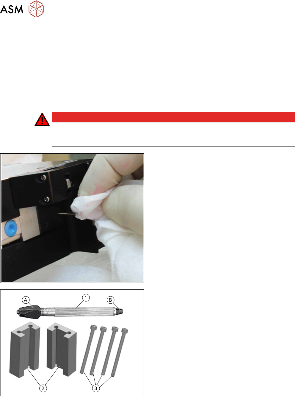
► Clean the jet plunger again with a cleansing tis-
sue and a little glue remover.
► Use the extraction tool set for the jet valve plun-
ger (item no. 03216329-xx) to reliably pull out the
plunger.
The extraction tool set includes:
●
Tool holder with square nut I=110 (item no.
03216547-xx) (1)
with a large (A) and a small (B)
clamping insert
●
2 guide profiles (2)
●
4 screws ISO 4762 – M3 x 40-A2-70 (item no.
03216547-xx) (3)
for fastening the guide profiles
5 Cleaning and Maintenance
5.6 Guide Bushing and Actuator O-Ring
User Manual SIPLACE Glue Feeder 05/2020 89
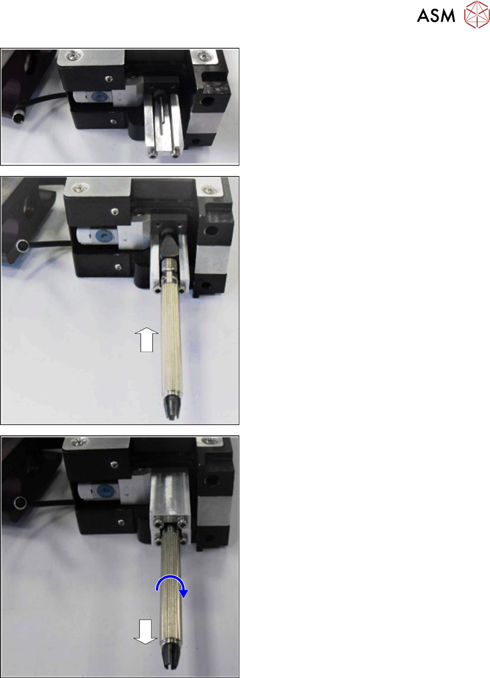
► Fit one of the guide profiles with the open side
pointing upwards (inner), using the screws
provided.
► Place the tool holder with the square nut onto the
guide profile.
Make sure that the square nut is fitted onto the smaller
(narrower) clamping insert.
► Push the tool holder up to the end stop on the
plunger.
► Fit the second guide profile with the open side
pointing downwards (inner), using the screws
provided.
► Turn the corrugated handle clockwise to tighten
the clamping nut.
► Pull the plunger straight out of the jet valve.
The heads of the screws fastening the guide profiles
prevent the tool holder from being pulled completely
out of the guide and possibly bent.