EUKYX-199-5100_G5S2_Instruction_Vol5_E.pdf - 第115页
199-5100 Chapt er 4 Circuit Diagrams This chapter describes the circuit diagrams. As this contains highly sophisticated contents, it should carefully be referred to. 1. Electrical and Electronic Symbols 2. Circuit Diagra…
EUKYX
3-21199-5100
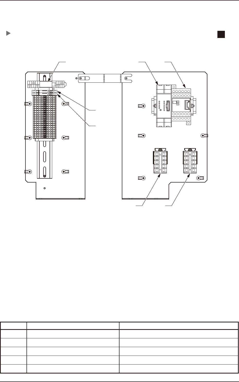
1.8 Side Panel (Rear)
1.8 Side Panel (Rear)
Symbol Name Remarks
K3
Safety Relay (Emergency Stop Switch)
K4
Safety Relay (Safety Cover, Feeder Cover)
K75 Block #1 Feeder Power ON Relay
K77 Block #2 Feeder Power ON Relay
K1B POWER ON Relay
K1B
K75 K77
K4 K3
F2
(6.3A)
F7
(6.3A)
5

199-5100
Chapter 4
Circuit Diagrams
This chapter describes the circuit diagrams.
As this contains highly sophisticated contents, it should carefully
be referred to.
1. Electrical and Electronic Symbols
2. Circuit Diagrams
EUKYX
EUKYX
4-1199-5100
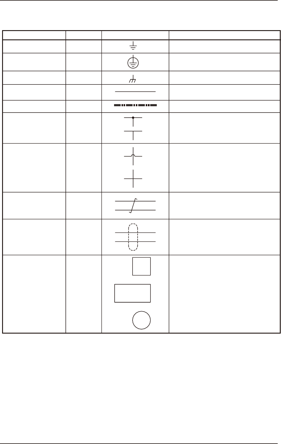
1. Electrical and Electronic Symbols
1. Electrical and Electronic Symbols
Name
Symbols
Graphical Symbols Remarks
Grounding (General)
Protective Ground
Connection (Chassis)
Cable
W
Optical Fiber Cable
Connection
No Connection
Twisted Pair
Shielding
Equipment or Device
“W” is used only for signal wires in block
diagrams.
The cables are connected electrically.
The cables are not connected electrically.
Signal wires are twisted.
Shielded Wires
(a)
(b)
(c)