EUKYX-199-5100_G5S2_Instruction_Vol5_E.pdf - 第119页
EUKYX 4-4 199-5100 1. Electrical and Electronic Symbols Name Relay Coil Contact (a) Contact (b) Contact (c) Coil (ON Delay) Contact a (Make Point) Contact a (Make Point) T imer Contact b (Break Point) Coil Main Contact (…
EUKYX
4-3199-5100
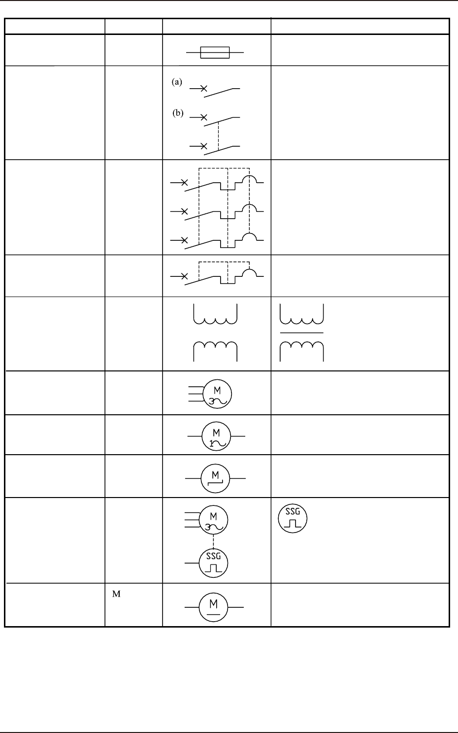
1. Electrical and Electronic Symbols
Name
Fuse
F
Q
Q
T
M
M
M
M
Breaker
Transformer
Transformers with iron
cores are used in the
machine and are expressed
as shown in the left figure.
DC Motor
Stepping Motor
Servo Motor
The left figure shows an encoder.
Three-Phase
Alternating Current
Motor
Single-Phase
Alternating Current
Motor Cooling Fan
Circuit Breaker
Circuit Protector
Air-Break Switch
Symbols
Graphical Symbols Remarks
EUKYX
4-4199-5100
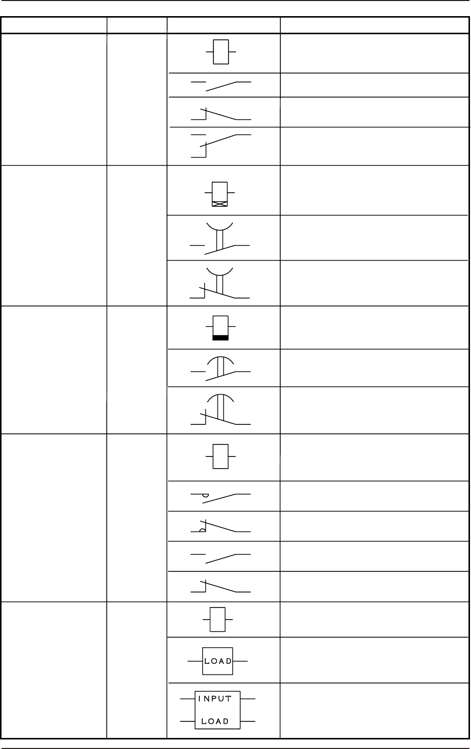
1. Electrical and Electronic Symbols
Name
Relay
Coil
Contact (a)
Contact (b)
Contact (c)
Coil (ON Delay)
Contact a
(Make Point)
Contact a
(Make Point)
Timer
Contact b
(Break Point)
Coil
Main Contact (a)
Main Contact (b)
Sub Contact (a)
Sub Contact (b)
INPUT
LOAD
A relay may be drawn using both
“INPUT” and “LOAD”.
Contact b
(Break Point)
Coil
(OFF Delay)
K
K
K
K
K
Timing Relay
(ON Delay)
Timing Relay
(OFF Delay)
Electromagnetic
Contactor
Solid-State Relay
Symbols
Graphical Symbols Remarks
EUKYX
4-5199-5100
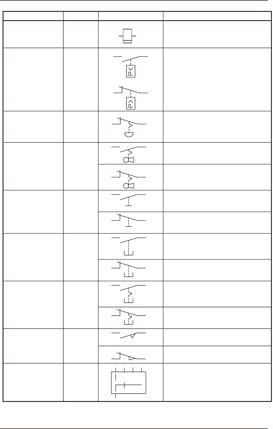
1. Electrical and Electronic Symbols
Name
Cycle Counter
Pressure Switch S
(a)
(b)
S
S
Key Switch
Contact a
Contact a
Contact a
Contact a
Contact a
Contact b
Contact b
Contact b
Contact b
The theory of contact combination
is described near the graphical symbol.
Contact b
Toggle Switch
Pushbutton Switch
(Momentary)
Pushbutton Switch
(Alternate)
Safety Door Switch
Limit Switch
Selector Switch
Emergency Stop
Button
Symbols
Graphical Symbols Remarks
S
S
S
S
S