EUKYX-199-5100_G5S2_Instruction_Vol5_E.pdf - 第151页
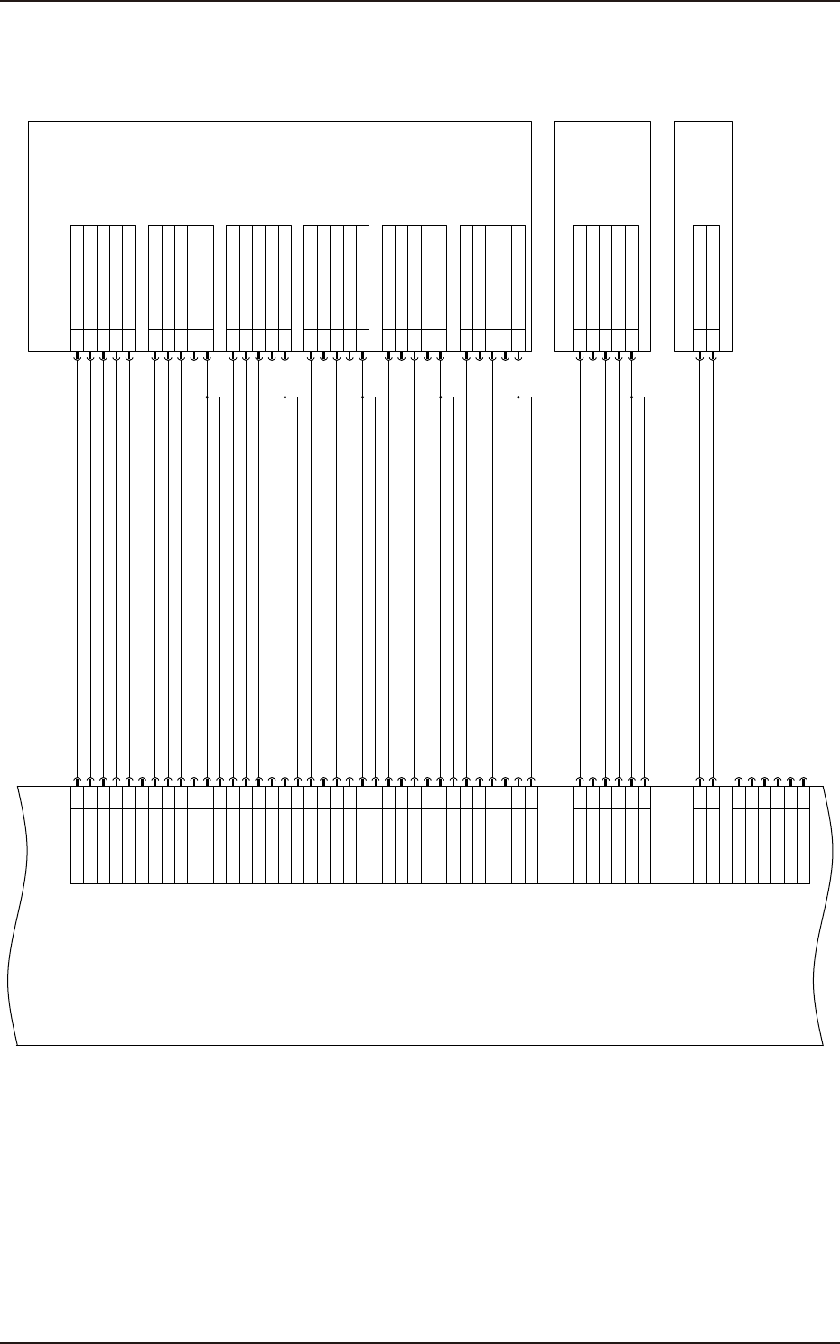
EUKYX 4-36 199-5100 2.21 U95 Connection Circuit 4 2. 21 U95 Conne ction Circuit 4 Transmission(Rear-Right) 1 Transmission(Rear-Left) 2 Transmission(Front-Left) 3 Transmission(Front-Right) 4 5 6 7 8 9 10 11 12 13 14 15 16…
EUKYX
4-35199-5100
2.20 U95 Connection Circuit 3
2.20 U95 Connection Circuit 3
1
2
3
4
5
6
7
8
9
10
11
12
13
14
15
16
17
18
19
20
21
22
23
24
+52V
N.C
+52V
+52V
+52V
+52V
+52V
+52V
31
32
33
34
35
36
37
38
39
40
41
42
+52V
+52V
+52V
+52V
25
26
27
28
29
30
+52V
+52V
43
44+52V
45
46
47
48
49
50
GND
(Fiducial Mark(Back))
+52V
+52V
9
10
11
12
13
14
15
16
17
18
19
20
21
22
23
24
25
26
27
28
29
30
1
2
3
4
5
6
7
8
Reflective upper (Rear)
Under Reflection(Rear)
+52V
+52V
+52V
Under Reflection(Front)
+52V
BGA Upper(Rear)
+52V
+52V
Reflective upper(Front)
Reflection Middle(Rear)
Reflection Middle(Front)
BGA Upper(Front)
BGA Lower(Rear)
BGA Lower(Front)
Component Recog.
Ring Lighting1
E191 (1)
1
2
3
4
5
+52V
Coax. Lighting(Rear)
Coax. Lighting(Left)
Coax. Lighting(Front)
Coax. Lighting(Right)
2
1
Reference Mark(Front)
+52V
Component
Recognition
Coax. Lighting
E192 (1)
Reference Mark
Lirgting1A
E193 (1)
1-XE192
1-XE193
1-XE191
X9505
CN5
OUT1-1
OUT1-2
OUT1-3
OUT1-4
OUT1-5
OUT1-7
OUT1-9
OUT1-11
OUT1-13
OUT1-15
OUT1-21
OUT1-23
OUT1-25
OUT1-27
OUT1-17
OUT1-18
OUT1-19
OUT1-20
OUT1-29
OUT1-30
Transmission(Rear-Right)
Transmission(Rear-Left)
Transmission(Front-Left)
Transmission(Front-Right)
N.C
N.C
N.C
N.C
N.C
N.C
N.C
N.C
N.C
N.C
N.C
N.C
N.C
N.C
N.C
N.C
N.C
N.C
N.C
N.C
N.C
N.C
N.C
U95
LED Light Control PCB
KYX-000-CC-018
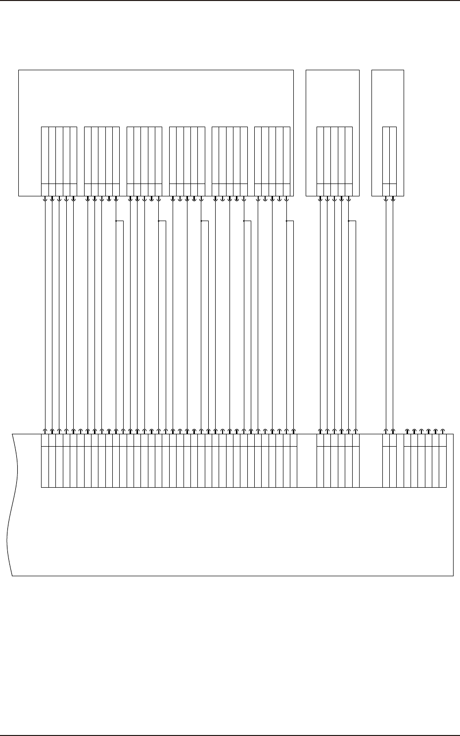
EUKYX
4-36199-5100
2.21 U95 Connection Circuit 4
2.21 U95 Connection Circuit 4
Transmission(Rear-Right)
1
Transmission(Rear-Left)
2
Transmission(Front-Left)
3
Transmission(Front-Right)
4
5
6
7
8
9
10
11
12
13
14
15
16
17
18
19
20
21
22
23
24
+52V
N.C
+52V
+52V
NC
+52V
+52V
+52V
+52V
31
32
33
34
35
36
37
38
39
40
41
42
+52V
+52V
+52V
+52V
25
26
27
28
29
30
+52V
+52V
43
44+52V
45
46
47
48
49
50
GND
(Fiducial Mark(Rear))
+52V
+52V
9
10
11
12
13
14
15
16
17
18
19
20
21
22
23
24
25
26
27
28
29
30
1
2
3
4
5
6
7
8
Reflective Upper(Rear)
Under reflection(Rear)
+52V
+52V
+52V
Under reflection(Front)
+52V
BGA Upper(Rear)
+52V
+52V
Reflective Upper(Front)
Reflection Middle(Rear)
Reflection Middle(Front)
BGA Upper(Front)
BGA Lower(Rear)
BGA Lower(Front)
Component Recog.
Ring Lighting2
E191 (2)
1
2
3
4
5
+52V
Coax. Lighting(Rear)
Coax. Lighting(Left)
Coax. Lighting(Front)
Coax. Lighting(Right)
2
1
Reference Mark Lighting(Front)
+52V
Component Recog.
Coax. Lighting2
E192 (2)
Reference Mark
Lighting1A
E193 (2)
2-XE192
2-XE193
2-XE191
X9506
CN6
OUT2-1
OUT2-2
OUT2-3
OUT2-4
OUT2-5
OUT2-7
OUT2-9
OUT2-11
OUT2-13
OUT2-15
OUT2-21
OUT2-23
OUT2-25
OUT2-27
OUT2-17
OUT2-18
OUT2-19
OUT2-20
OUT2-29
OUT2-30
N.C
N.C
N.C
N.C
N.C
N.C
N.C
N.C
N.C
N.C
N.C
N.C
N.C
N.C
N.C
N.C
N.C
N.C
N.C
N.C
N.C
U95
LED Light Control PCB
KYX-000-CC-019
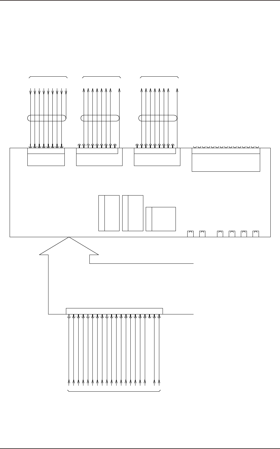
EUKYX
4-37199-5100
2.22 CPU2 U81 Connection Circuit
2.22 CPU2 U81 Connection Circuit
8
7
4
6
5
2
3
1
N.C.
N.C.
TD+
RD+
TD-
N.C.
RD-
N.C.
CN8
X8102
LAN
8
9
7
4
6
5
2
3
1
Case
CN1-1
CTS
RI
RTS
DCD
TxD
RxD
GND
DSR
DTR
SERIAL1
X8104
8
9
7
4
6
5
2
3
1
Case
CN1-2
X8109
1
3
2
5
6
4
7
10
11
12
13
14
15
9
8
CN3
N.C.
GND
GND
GREEN
BLUE
RED
GND
DDC VCC
GND
N.C.
DDC DAT
H-SYNC
V-SYNC
DDC CLK
GND
VGA
KEY(PS/2)
XG22P1
J1
J2
1
2
3
4
5
6
7
8
9
10
11
12
13
14
15
16
17
18
19
20
U180
MOUSE(PS/2)
USB1
USB2
USB3
USB4
CN7
CTS
RI
RTS
DCD
TxD
RxD
GND
DSR
DTR
SERIAL2
CF
D81
CN6
CN5
CN4
CN2-2
CN2-1
U81
CPU
(512MB)
J6
J8(Upper)
DIMM Memory
J7(Lower)
DIMM Memory
(512MB)
Unimplemented
+3.3VDC
+3.3VDC
GND
+5VDC
GND
+5V SB
+12VDC
+3.3VDC
+3.3VDC
+3.3VDC
-12VDC
GND
GND
GND
+5VDC
+5VDC
+5VDC
GND
[R-/01/4F]
from G21-MAIN
[B-/06/1D]
to X30B-X30C2
[R-/01/7B]
from U91-LAN2
:3
:2
:4
:5
:6
:7
:8
FG
[B-/07/1D]
to X30F-X30C2
:3
:2
:4
:5
:6
:7
:8
FG
:1
:6
:7
:2
:8
:4
:FG
:5
:3
CPCI-bus
PSU_POWER OK
KYX-000-CC-020