EUKYX-199-5100_G5S2_Instruction_Vol5_E.pdf - 第169页
EUKYX 4-54 199-5100 2.39 (B2) Cutter Connection Circuit 2. 39 ( B2 ) Cut ter Connection C ircuit 1 2 A63F 1 2 24V SIGNAL_A SIGNAL_B GND CN12 24V(24B4) SIGNAL_A SIGNAL_B GND(10) +V OUT1 GND :1 B6302 :A4 :A3 :B3 :A2 [N-/04…
EUKYX
4-53199-5100
2.38 (B1) Cutter Connection Circuit
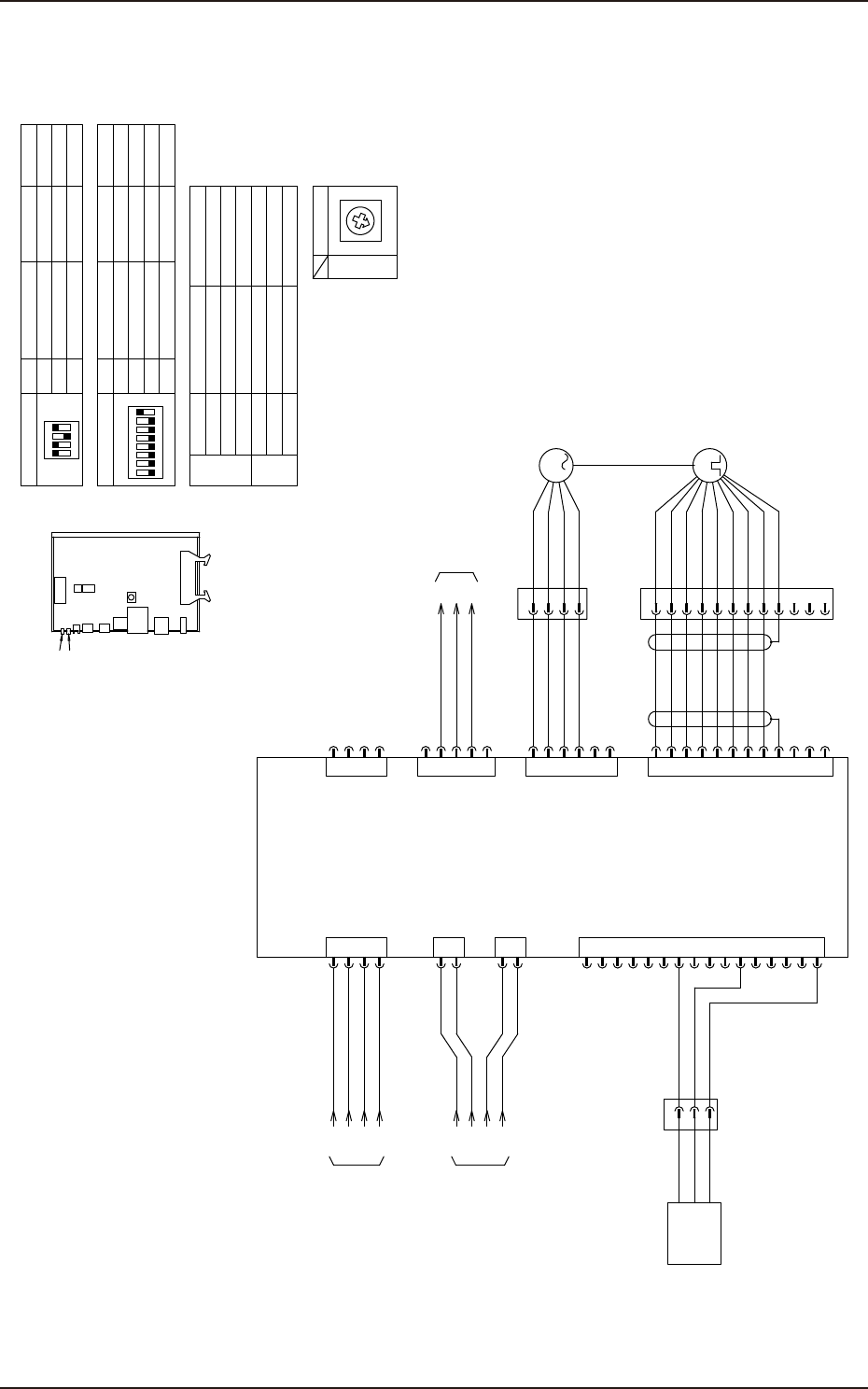
2.38 (B1) Cutter Connection Circuit
1
2
A63B
1
2
24V
SIGNAL_A
SIGNAL_B
GND
CN12
24V(24B4)
SIGNAL_A
SIGNAL_B
GND(10)
+V
OUT1
GND
Cutter-Axis.
origin sensor
:1
B6302
:A4
:A3
:B3
:A2
[N-/01/7A]
AE-LINK
from U27-CN18
[B-/03/8C]
[B-/06/5C]
to X30D3B
Servo Motor AMP
X6312B
4
3
2
1
CN1
X6301B
48V(48D3)
GND
CN11
X6311B
24V(24A6)
GND
:1
:2
:3
:4
1
CN7
X6307B
GND
2
AIN
3
Reserve_PLS+
4
5
Forward_PLS+
6
7
GND
8
AUX
9
C_RST
10
RST
11
Reserve_LMT
12
Forward_LMT
13
SVON
14
INP
15
ALM
16
24V
GND
AIN
Reserve_PLS-
Forward_PLS-
:2
:3
4
3
2
1
CN14
GND
CAN_L
GND
CAN_H 4
3
2
1
CN2
24V 5
U
V
W
FG 4
3
2
1
CN3
BK 5
BK 6
S2
S4
S1
S3 B2
A2
B1
A1
CN5
R1 A3
R2 B3
A6
B5
GND B6
A4
B4
A5
3
M
SSG
:A1
:B1
:A2
:B2
:A3
:B3
:B5
:A6
:B6
:A4
:B4
:A5
:1
:2
:3
:4
:1
:3
:2
M63 (B1)
Cutter-Axis.
SW2
SW3
SW1
LED2
LED1
1
ON
2 3 4
A63B External view
1
ON
2 3 4
5 6 7 8
OFF
6 For testing
7
MAC-ID assignment
8
Communication
(Lighting up)
Servo OFF
Green
(Flashing)
Servo ON
Warning
Alarm
Drive power shutdown
LED1
Control side
Checking driver connection
LED2
During control side
1~5 unused
OFF
OFF
ON
NO. Setting contents Configuration Remarks
Fixed ID
307.2Kbps
SW3
Remarks
ON
3 unused
4
SV-NET Termination
1,2
AE-LINK Termination
OFF
NO. Setting contents Configuration RemarksSW2
ON
MAC-ID:1
8
7
6
5
4
3
2
1
0
F
E
D
C
B
A
9
A63B
SW1
XM63
XM63P
B6302
X6302F
X6303F
X6305F
Speed setting
Orange
(Lighting up)
Red/Green
(Flashing)
Red
(Lighting up)
Orange
(Lighting up)
Green
(Lighting up)
Communication stop
Communication
KYX-000-CC-035
EUKYX
4-54199-5100
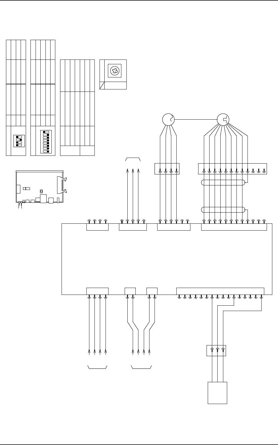
2.39 (B2) Cutter Connection Circuit
2.39 (B2) Cutter Connection Circuit
1
2
A63F
1
2
24V
SIGNAL_A
SIGNAL_B
GND
CN12
24V(24B4)
SIGNAL_A
SIGNAL_B
GND(10)
+V
OUT1
GND
:1
B6302
:A4
:A3
:B3
:A2
[N-/04/7B]
From A10-N2
from U27-CN19
[B-/03/8C]
[B-/07/5C]
to X30D3F
Servo Motor AMP
X6312F
4
3
2
1
CN1
X6301F
48V(48D3)
GND
CN11
X6311F
24V(24A6)
GND
:1
:2
:3
:4
1
CN7
X6307F
GND
2
AIN
3
Reserve_PLS+
4
5
Forward_PLS+
6
7
GND
8
AUX
9
C_RST
10
RST
11
Reserve_LMT
12
Forward_LMT
13
SVON
14
INP
15
ALM
16
24V
GND
AIN
Reserve_PLS-
Forward_PLS-
:2
:3
4
3
2
1
CN14
GND
CAN_L
GND
CAN_H 4
3
2
1
CN2
24V 5
U
V
W
FG 4
3
2
1
CN3
BK 5
BK 6
S2
S4
S1
S3 B2
A2
B1
A1
CN5
R1 A3
R2 B3
A6
B5
GND B6
A4
B4
A5
3
M
SSG
:A1
:B1
:A2
:B2
:A3
:B3
:B5
:A6
:B6
:A4
:B4
:A5
:1
:2
:3
:4
:1
:3
:2
M63 (B2)
Cutter-Axis.
XM63
XM63P
X6302F
X6303F
X6305F
Cutter-Axis.
origin sensor
B6302
SW2
SW3
SW1
LED2
LED1
1
ON
2 3 4
A63F External view
1
ON
2 3 4
5 6 7 8
OFF
6 For testing
7
MAC-ID assignment
8
Communication
(Lighting up)
Servo OFF
Green
(Flashing)
Servo ON
Warning
Alarm
Drive power shutdown
LED1
Control side
Checking driver connection
LED2
During control side
1~5 unused
OFF
OFF
ON
NO. Setting contents Configuration Remarks
Fixed ID
307.2Kbps
SW3
Remarks
ON
3 unused
4
SV-NET Termination
1,2
AE-LINK Termination
OFF
NO. Setting contents Configuration RemarksSW2
ON
MAC-ID:1
8
7
6
5
4
3
2
1
0
F
E
D
C
B
A
9
A63F
SW1
Speed setting
Orange
(Lighting up)
Red/Green
(Flashing)
Red
(Lighting up)
Orange
(Lighting up)
Green
(Lighting up)
Communication stop
Communication
KYX-000-CC-036
EUKYX
4-55199-5100
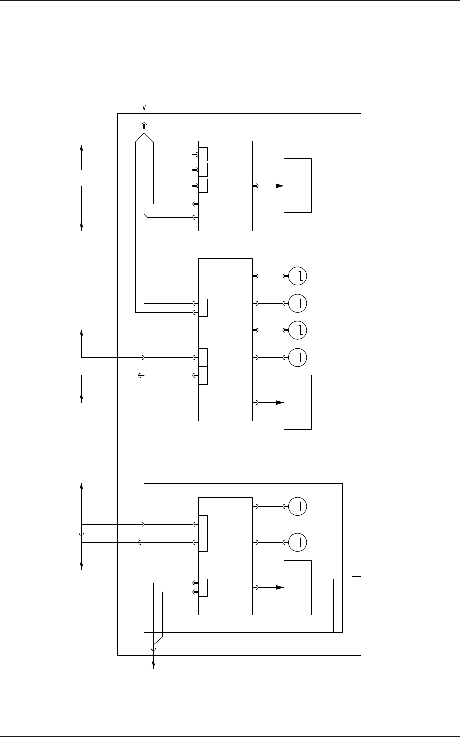
2.40 Single Transfer Block Diagram
2.40 Single Transfer Block Diagram
A11
Stepping Motor Driver
M45 M46
NA_BL NA_BR
MM
Connection when installing Backup base OP
XAE2CH XAE_CT
CN1 CN5
U85-2CH
N1 N2
AE-LINK
24A6
48D
Conveyor Unit
Load / sensor
Servo Motor AMP
A63F
XAE2CH XAE_CT
Backup base OP
Note 1:
Single Conveyor Unit
POWER
CN10
XCV-R
DC24,48V
A10
Stepping Motor Driver
M41 M42 M43 M44
NL_L NA_L NR_L NA_W
MMMM
X1X2
Conveyor Unit
Load / sensor
U08
IO PCB
Bundle Connector
XAE1CH XAE_CT
CN7 CN8 CN9 CN10
CN1
UP
CN2
DN
CN3
T
U85-T(X85T) X30C1-BU85-1CH
Servo Motor AMP
A63B
N1 N2
AE-LINK
Conveyor Unit
Load / sensor
24A6
48D
24A3
XCV-L
DC24,48V
POWER
CN6
HSIO
KYX-000-CC-037