EUKYX-199-5100_G5S2_Instruction_Vol5_E.pdf - 第71页
EUKYX 1-22 199-5100 2.1 1 Multi-Functional Head Unit NOZZLE1 NOZZLE2 NOZZLE3 7 10 12 2. 1 1 Multi-Functional Head Unit No. Name Q’ty No. Name Q’ty No. Name Q’ty No. Name Q’ty 7 Regulator 1 10 Solenoid V alve Unit 3 12 V …
EUKYX
1-21199-5100
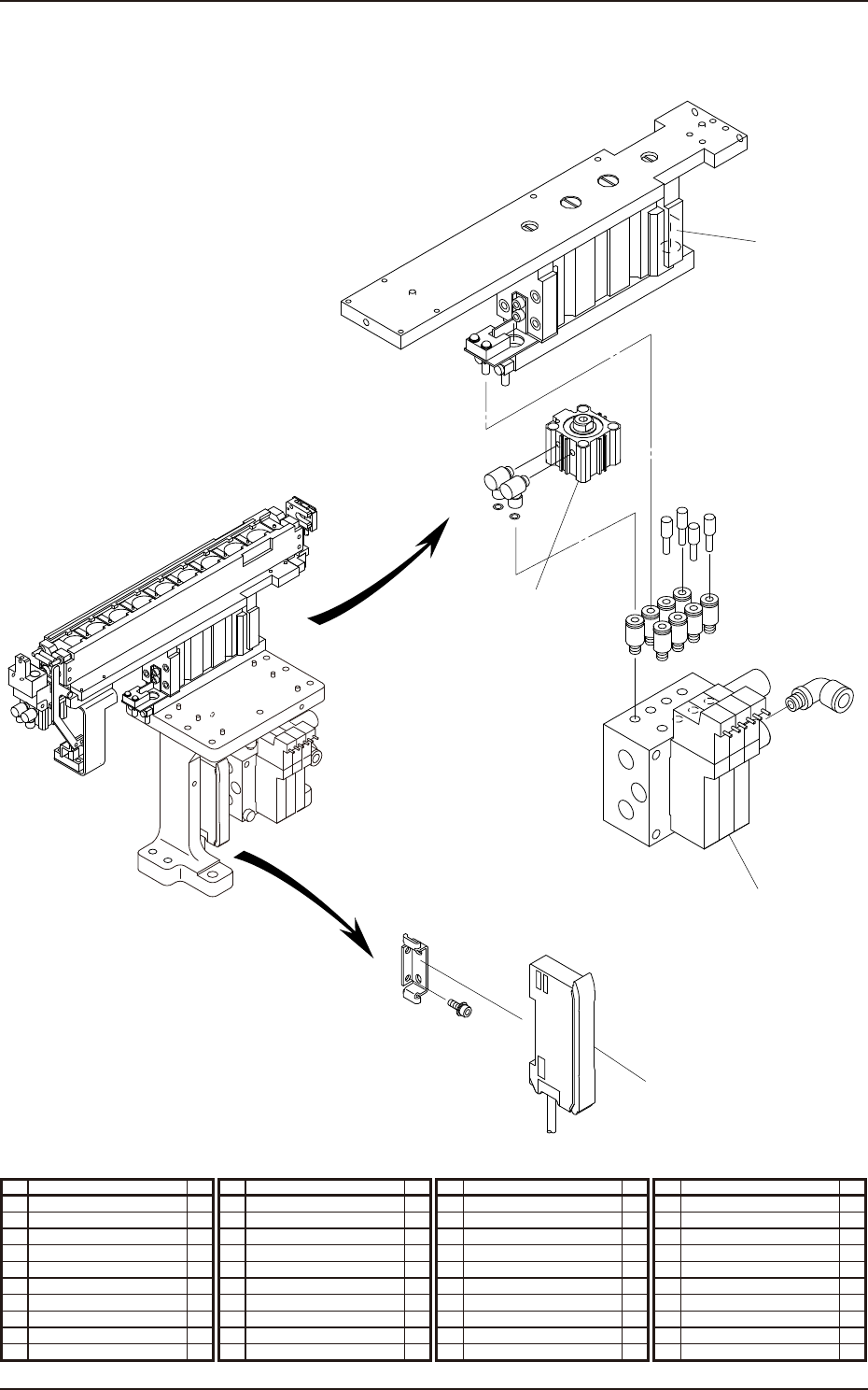
2.10 Nozzle Stocker for Multi-Functional Nozzle
2
1
3
4
2.10 Nozzle Stocker for Multi-Functional Nozzle
No. Name Q’ty No. Name Q’ty No. Name Q’ty No. Name Q’ty
1 Solenoid Valve 3
2 Cylinder 1
3 Cylinder 1
4 Sensor Amplier 1
EUKYX
1-22199-5100
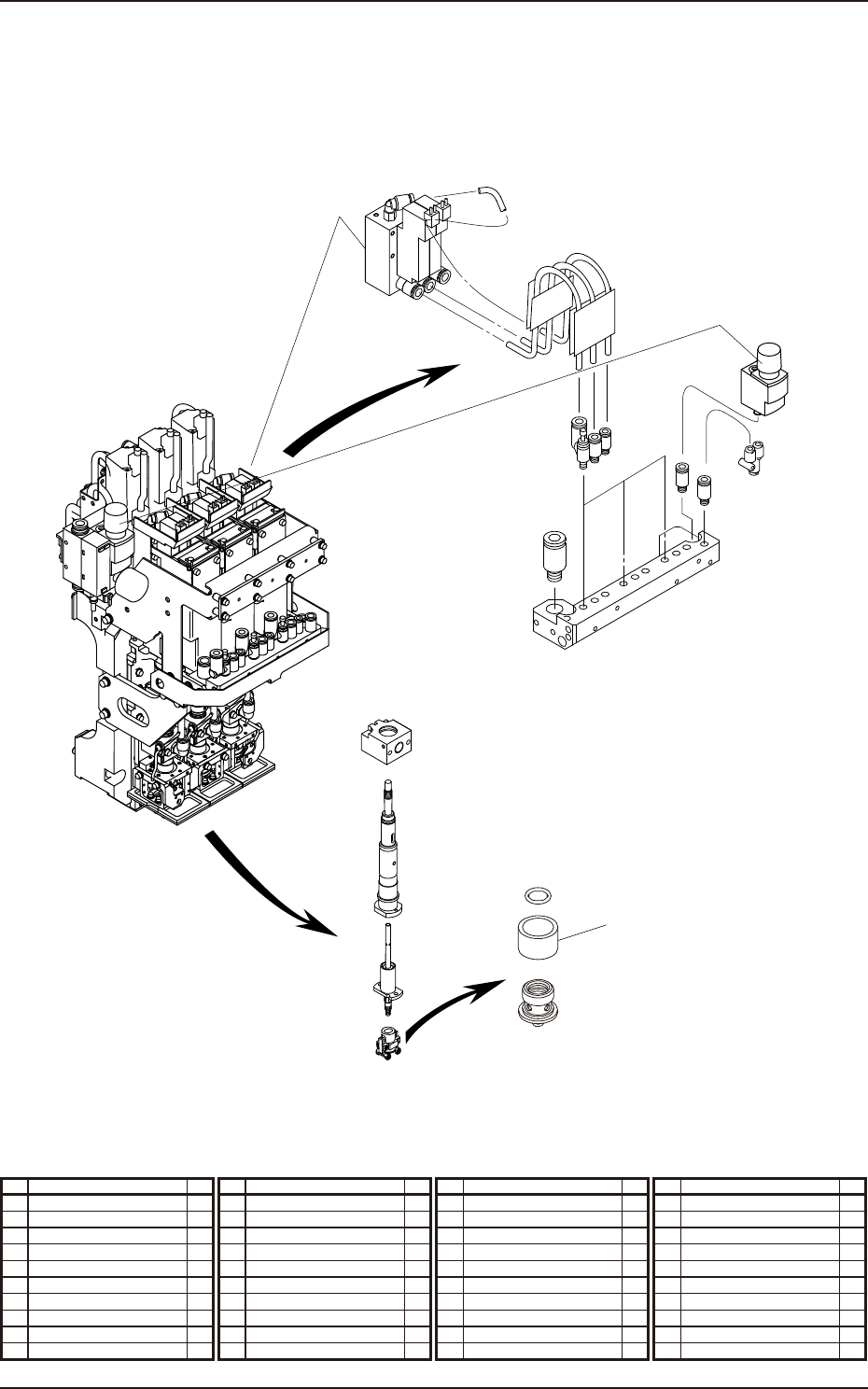
2.11 Multi-Functional Head Unit
NOZZLE1
NOZZLE2
NOZZLE3
7
10
12
2.11 Multi-Functional Head Unit
No. Name Q’ty No. Name Q’ty No. Name Q’ty No. Name Q’ty
7 Regulator 1
10 Solenoid Valve Unit 3
12 Vacuum Filter 3

199-5100
Chapter 2
Sensor and Load Layout
This chapter indicates where the sensors and loads are located
in each section. As this contains highly sophisticated contents, it
should carefully be referred to.
1. Sensor and Load Layout
EUKYX