wire-bonder.pdf - 第108页
WEST•BOND MODEL 454647E SER IES INSTRUCTION MANUAL 102 TOOL HEAD CONVERSION 45 ° to 90 ° Tool Head Conversion The 454647E offers the ability to wire bond with the 45 degree wire f eed tool assembly or the Deep Access wir…
WEST•BOND MODEL 454647E SERIES INSTRUCTION MANUAL
101
TROUBLESHOOTING
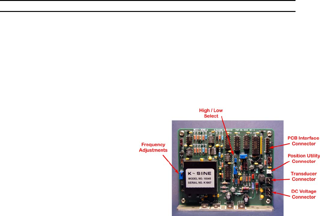
Ultrasonic Board (P/N A-10345)
IN-MACHINE CALIBRATION
1. Equipment required:
1.1 An oscilloscope.
1.2 A multi-meter (true RMS voltages up to 100 KHz).
1.3 20 Ohm resistor, 5 Watt minimum.
* All following measurements are made with respect to circuit common TP1*
2. DC voltage verification:
2.1 Turn on bonder main power and leave it idle at home.
2.2 Using DC volt meter, verify the DC
voltages as follows:
• At J3 pin 1 for -15 VDC
• At J3 pin 3 for +15 VDC
• At TP6 for -5 VDC
• At TP7 for +5 VDC
• At TP3 for -1.2 VDC
• At TP5 for 0 VDC
3. Oscillator calibration:
3.1 Disconnect transducer at connector
J2.
3.2 Connect the oscilloscope probe to
TP2.
3.3 Verify that the signal is a 5V square
wave.
3.4 Adjust potentiometer RT1 till the scope reads about 63.5 KHz (15.75uS).
4. Output voltage calibration:
4.1 Connect a 20 Ohm, 5 Watt resistor across pin 1 and pin 2 of connector J2. Take care not to short
across 2 pins.
4.2 Connect AC volt meter and oscilloscope probes to TP5.
4.3 Connect jumper E1 pin1 to pin 2 (high power output).
4.4 Remove PCB Interface (J1)
4.5 Connect a jumper wire from J1-pin1 to TP7 (5vdc)
4.6 Verify that the meter reads .038 Vrms (0.100 Vp-p) and scope shows a clean sine wave.
4.7 Adjust RT4 to obtain the reading
4.8 Remove jumper and reconnect J1
4.9 Program selected channel to have bond power 999 (full power) and bond time 999 (999mS).
4.10 While trigger the selected channel, verify that the meter reads 8 Vrms (22.63Vp-p) and scope
shows a clean sine wave. Adjust RT2 to obtain the reading.
4.11 Connect jumper E1 pin 2 to pin 3 (low power output).
4.12 While trigger the selected channel, verify that the meter reads 4.5 Vrms (12.73Vp-p). Adjust RT3
to obtain the reading.
5. Final check:
5.1 Remove 20 Ohm resistor at connector J2 and connect machine transducer to it.
5.2 Return jumper E1 pin connections to original position.
5.3 Connect Oscilloscope to TP5 and trigger ultrasonics and verify frequency of <65KHz.
5.4 Remove all test leads.
5.5 Press the machine reset switch or recycle machine main power, verify that there is no error
message from the machine.
WEST•BOND MODEL 454647E SERIES INSTRUCTION MANUAL
102
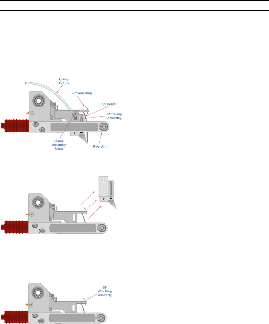
TOOL HEAD CONVERSION
45
°
to 90
°
Tool Head Conversion
The 454647E offers the ability to wire bond with the 45 degree wire feed tool assembly or the Deep
Access wire feed tool assembly. The conversion process from one tool assembly to another should take
approximately 5 minutes. Please review the following instructions to insure proper execution of the
exchange on our 454647E wire bonder.
1) Remove the bonding tool.
Disconnect the Clamp Air Line from
the front cover panel and the small
clamp securing the hose to the side
of the head assembly.
2) Holding the Tooling Head remove
the clamp release screw and
remove clamp assembly.
3) If not already done, Insert the Wire
Drag Assembly. Position the wire
drag tube so that it lines up
front/back and left/right with the
transducer hole for the bonding
tool.
WEST•BOND MODEL 454647E SERIES INSTRUCTION MANUAL
103
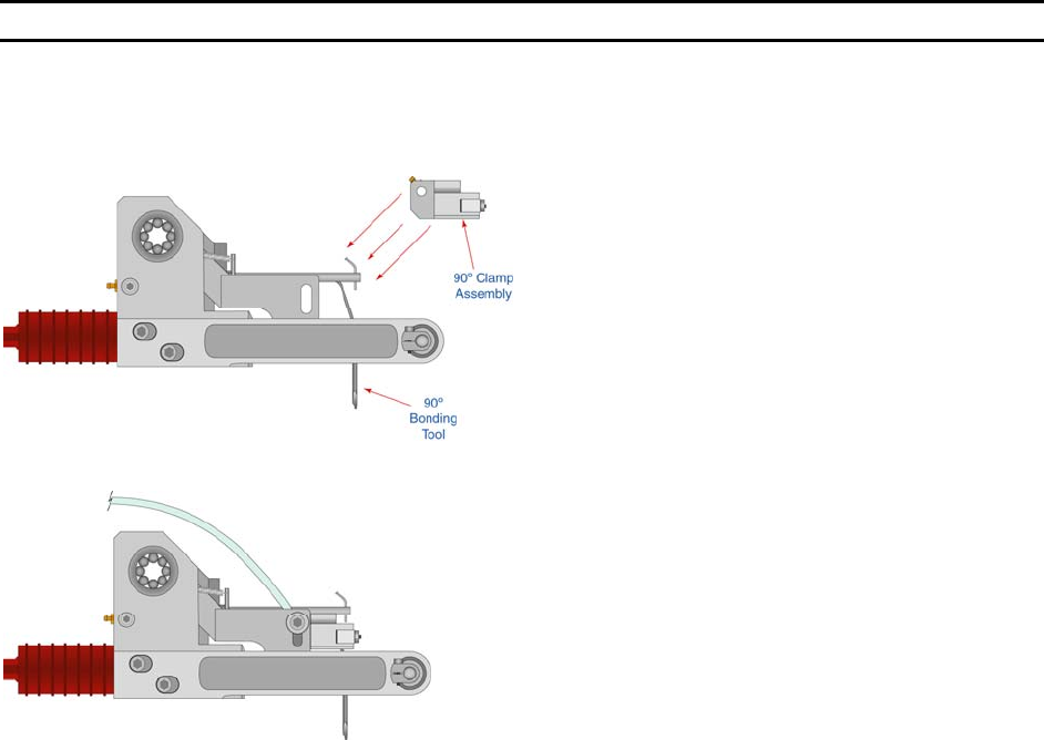
TOOL HEAD CONVERSION
45
°
to 90
°
Tool Head Conversion
4) Insert the 90° clamp assembly into
the location the 45° clamp
assembly was just removed from.
Insert the Clamp Screw to secure
clamp assembly. Align the clamp
assembly, so that the top surface
of the clamps are flush with the top
of the mounting surface. Tighten
the Clamp Screw.
5) Connect the Clamp Air Line to the
front cover panel. Verify the
Alignment and actuation of the
Clamp Assembly is correct for
proper bonding.
6) Change Model Number for
selected clamp assembly. (See
page 105).
90
°
to 45
°
Tool Head Conversion
REVERSE THE ABOVE STEPS (PAGES 102 TO 103 ) TO RE-INSTALL THE 45
°
TOOLING HEAD CLAMP ASSEMBLY
A) Position the new 45° Tooling Head so that the Top and Front sides are flush with the Clamp
Screw Block.
B) Align the clamps so that the wire feeds at 45° through the transducer, clamps and tool.
Please do not hesitate to contact your local Sales/Service representative for assistance or call the
W
EST•BOND factory at (714) 978-1551 and ask for the service department.