wire-bonder.pdf - 第109页
WEST•BOND MODEL 454647E SERIES INSTRUCTION MANUAL 103 TOOL HEAD CONVERSION 45 ° to 90 ° Tool Head Conversion 4) Insert the 90 ° cla mp assembly into the location the 45 ° clamp assembly was just removed from. Insert the …
WEST•BOND MODEL 454647E SERIES INSTRUCTION MANUAL
102
TOOL HEAD CONVERSION
45
°
to 90
°
Tool Head Conversion
The 454647E offers the ability to wire bond with the 45 degree wire feed tool assembly or the Deep
Access wire feed tool assembly. The conversion process from one tool assembly to another should take
approximately 5 minutes. Please review the following instructions to insure proper execution of the
exchange on our 454647E wire bonder.
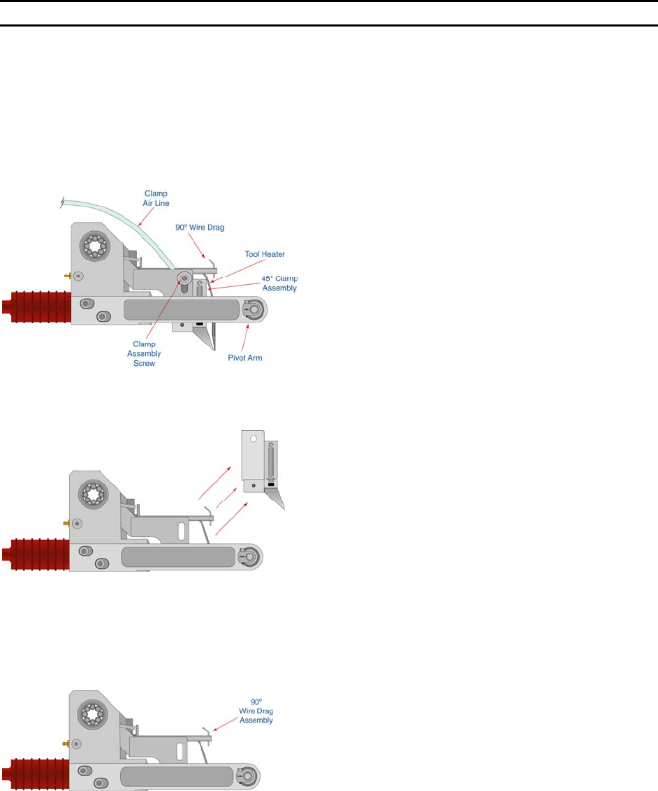
1) Remove the bonding tool.
Disconnect the Clamp Air Line from
the front cover panel and the small
clamp securing the hose to the side
of the head assembly.
2) Holding the Tooling Head remove
the clamp release screw and
remove clamp assembly.
3) If not already done, Insert the Wire
Drag Assembly. Position the wire
drag tube so that it lines up
front/back and left/right with the
transducer hole for the bonding
tool.
WEST•BOND MODEL 454647E SERIES INSTRUCTION MANUAL
103
TOOL HEAD CONVERSION
45
°
to 90
°
Tool Head Conversion
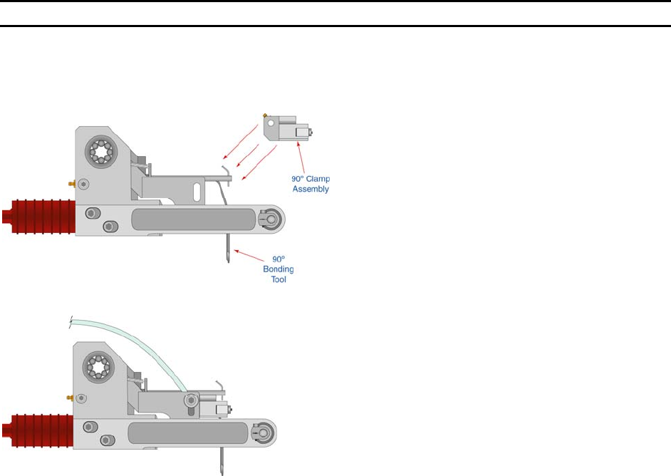
4) Insert the 90° clamp assembly into
the location the 45° clamp
assembly was just removed from.
Insert the Clamp Screw to secure
clamp assembly. Align the clamp
assembly, so that the top surface
of the clamps are flush with the top
of the mounting surface. Tighten
the Clamp Screw.
5) Connect the Clamp Air Line to the
front cover panel. Verify the
Alignment and actuation of the
Clamp Assembly is correct for
proper bonding.
6) Change Model Number for
selected clamp assembly. (See
page 105).
90
°
to 45
°
Tool Head Conversion
REVERSE THE ABOVE STEPS (PAGES 102 TO 103 ) TO RE-INSTALL THE 45
°
TOOLING HEAD CLAMP ASSEMBLY
A) Position the new 45° Tooling Head so that the Top and Front sides are flush with the Clamp
Screw Block.
B) Align the clamps so that the wire feeds at 45° through the transducer, clamps and tool.
Please do not hesitate to contact your local Sales/Service representative for assistance or call the
W
EST•BOND factory at (714) 978-1551 and ask for the service department.
WEST•BOND MODEL 454647E SERIES INSTRUCTION MANUAL
104
TOOL HEAD CONVERSION
Wedge to Ball Bonder Tool Head Conversion
The 454647E also offers the ability to change the entire head assembly to covert the machine into a ball
bonder. The conversion process from one head assembly to another should take approximately 10
minutes. Please review the following instructions to insure proper execution of the exchange on our
454647E wire bonder.
1) Remove bonding tool, disconnect the air hose
and both connectors from the front panel cover.
Also remove the small clamp on the left side of
the head holding the air hose to the tool head
plate.
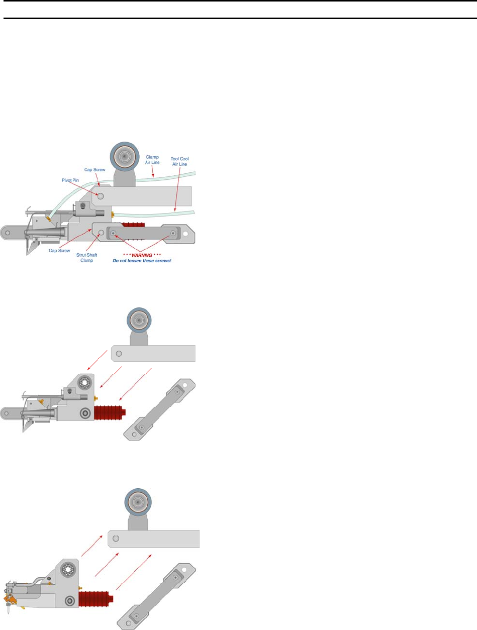
2) Disconnect the FORCE STRUT ARM from the head
assembly. The F
ORCE STRUT ARM is connected to
the head assembly with a Dutch Key Assembly to
the C
LAMP, STRUT SHAFT (P/N 8086) on the right
side of the tooling head. To remove loosen the
cap screw on the front side of the Clamp and
push the pin (S
HAFT, STRUT P/N 7952.001) inside
and then lower the FORCE STRUT ARM to a
relaxed position. Do not pull the
FORCE STRUT
ARM excessively to the right. Excessive pull to
the right could induce drag against the tooling
head when reassembled. Do not loosen the two
button head screws, these are set at the factory
for head perpendicularity.
3) Maintain a secure grip of the tooling head and
loosen the CAP SCREW securing the pivot pin
located on the top right hand side to the tooling
head. This C
AP SCREW need only be loosened
sufficiently to allow the PIVOT PIN to slide to the
right. Once the P
IVOT PIN been releases and
slides to the right the tooling head will be free and
may be removed. Do Not remove the C
AP SCREW
or P
IVOT PIN. It is not necessary to remove the
C
AP SCREW and PIVOT PIN from the tooling head
in order to remove the tooling head. As you drop
the head away from the machine disconnect the
T
OOL COOL air hose attached at the rear of the
head.
4) Reattach the TOOL COOL to the back of the BALL
BOND HEAD and gently maneuver the BALL BOND
HEAD assembly between the fixed and loose
P
IVOT PINS. Using two Allen wrenches push the
loose P
IVOT PIN with one wrench and then tighten
the C
AP SCREW with the other. There should be
no side-to-side play of the head assembly.