wire-bonder.pdf - 第17页
WEST•BOND MODEL 454647E SER IES INSTRUCTION MANUAL 11 INSTALLATION Unpacking and Inspection S TEP 1 Remove the accessory box, identify, and account for all conte nts. 3 ITEM OPTION 3 ITEM OPTION Mani p ulator Control Arm…

WEST•BOND MODEL 454647E SERIES INSTRUCTION MANUAL
10
CAUTIONS
Micromanipulator
The hand controls on your WEST•BOND machine have been designed for minimal exertion of the hand
and fingers. The position of the control knob is purposely set to coincide with a natural rest position of the
hand (fetal position). During operation, the operator should rest his/her hand, wrist, and forearm on the
tabletop so that the thumb, index and middle fingers gently grip the manipulator knob. With the work
piece centered in the microscope, and the tool centered to the optics, usual movement or excursion of the
manipulator is usually within plus or minus one-half inch, which is well within natural flexure of the thumb
and fingers gripping the control knob. The force required to move the mechanism is somewhat equivalent
to pushing a pencil while writing. Following the recommendations set forth in “Exercises” above vastly
relieves any perception of muscle fatigue.
The last key point; all these guidelines should be applied to your home work station and home activities,
particularly home computers. They should also be applied to video games and your recreational
television viewing.
After a long day at work, your body does not need more of the same type of activity when you return
home. Remember, diversity of physical activity may well be the simplest and most meaningful
recommendation to avoid repetitive stress syndrome such as carpal tunnel syndrome.
WEST•BOND MODEL 454647E SERIES INSTRUCTION MANUAL
11
INSTALLATION
Unpacking and Inspection
STEP 1
Remove the accessory box, identify, and account for all contents.
3
ITEM OPTION
3
ITEM OPTION
Mani
p
ulator Control Arms standard
A
ir Re
g
ulator standard
Ke
y
Pad standard
A
dditional Wire Clam
p
s
(
90°
)
standard
Video Monitor standard
A
dditional Ball Bond Head standard
Camera standard Microsco
p
e
(
o
p
tional
)
Camera Cables standard Illuminator
(
o
p
tional
)
NEFO Unit standard Work Holder
(
o
p
tional
)
Crosshair Generator standard Temperature Controller (optional)
STEP 2
Remove the accessory pedestal insert and carefully lift the
454647E and the attached shipping board from the bottom of
the shipping carton.
S
TEP 3
Remove the six shipping bolts that fasten the 454647E to the
shipping board.
N
OTE! Save all packing material for use during any
future equipment relocation
S
TEP 4
Position the 454647E where it will be used.
S
TEP 5
Remove the cover of the X-Y-Z Assembly unit to gain access
to the shipping blocks.
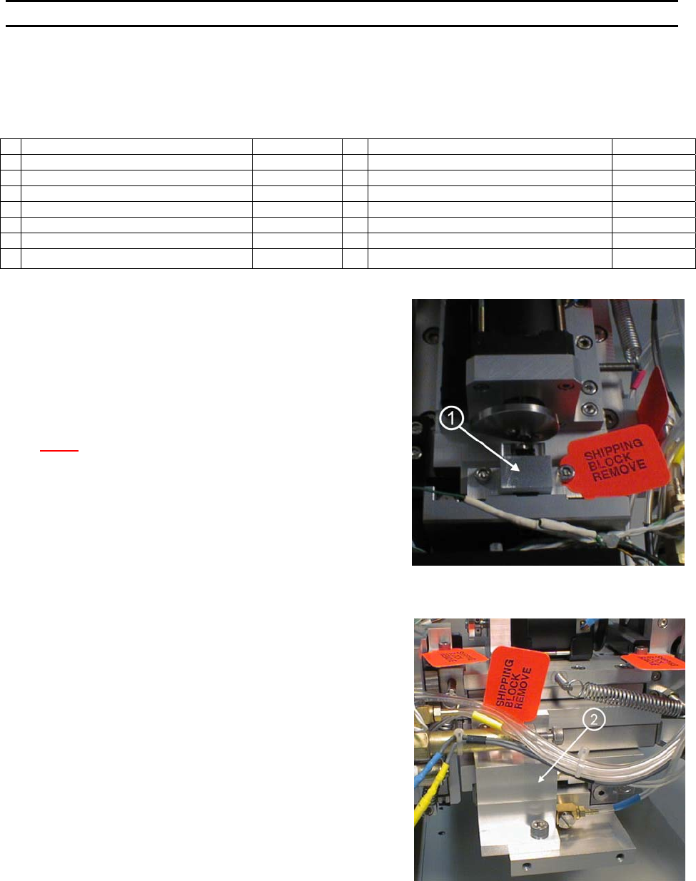
S
TEP 6
Remove the two Z-Mount Shipping Brackets (P/N’s 9081 and
9082) ← located just behind and below the microscope
mount. Remove the two shipping cap screws to remove the
brackets.
S
TEP 7
Remove the X Mount Shipping Bracket (P/N 9079) ↑ located
behind and just below the dual force cylinder. Remove the
shipping cap screw at the bottom and two more at the top of
the bracket.
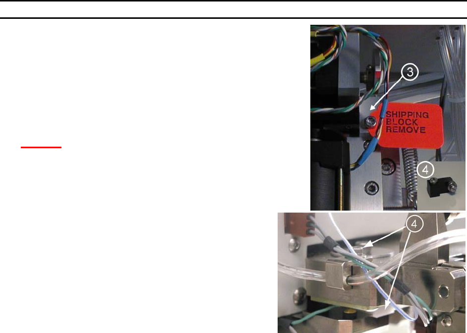
S
TEP 8
Remove the Y-Mount Shipping Bracket (P/N 9080) → located
at the back of the X-Y-Z Assembly. Remove the two shipping
cap screws. Replace the Shipping bracket with the Cam
Follower Mount Y-Slide (P/N 8928) ↓, Tie Wrapped to the X-
Y-Z Cover.
WEST•BOND MODEL 454647E SERIES INSTRUCTION MANUAL
12
INSTALLATION
Unpacking and Inspection
STEP 9
Locate the micromanipulator arm from the accessory box and install
it in the mounting collar. Tighten the two mounting collar cap screws
with approximately equal force. The vertical registration pin in the
mounting collar should interconnect with the manipulator to insure
correct installation.
C
AUTION! Never attempt to lift the machine by the
micromanipulator arm!
S
TEP 10
Remove the Firing Switch Shipping Block (P/N 6873.002)
f located
under the tooling head. Remove the cap screw and washer on top
of the tool head. Gently pull the shipping block free, being
careful not to harm the transducer.
Connecting the Accessories
STEP 1 - AIR
Connect ¼” poly-flow tubing from air regulator to rear panel fitting.
Adjust for approximately 50 psi nominal.
S
TEP 2 - MICROSCOPE
Attach the Microscope Mount to the Microscope Support, located in the center of the machine, using the
screw and washer provided. Position the Mount so that it is completely forward, close to the operator.
Attach the Microscope to the Microscope Arm assembly. Adjust the arm to place the Microscope in the
maximum up position. Attach the Illuminator to the Microscope using the adapter which threads into the
Microscope. Position the wire for the Illuminator in the direction of the Microscope Arm Assembly, away
from the operator.
Place the Microscope into the Microscope mount on the machine using caution not to interfere with the
video camera assembly.
After all accessories are connected and the machine is ready to bond, the Microscope needs to be
adjusted and properly centered. (See Thread and Bond-Off Section, page 33).
S
TEP 3 - VIDEO CROSSHAIR GENERATOR
Connect the BNC cable from the V
IDEO OUT connector of the Crosshair Generator to the VIDEO IN
connector on the Video Monitor. Plug in both units to 110VAC, 50-60Hz.