wire-bonder.pdf - 第19页
WEST•BOND MODEL 454647E SER IES INSTRUCTION MANUAL 13 INSTALLATION Connecting the Accessories S TEP 4 - C AMERA Check Camera (Horizontally Mounted). Make sure the Camera Body and Lens Assembly are perpendicular to X-Y Pl…
WEST•BOND MODEL 454647E SERIES INSTRUCTION MANUAL
12
INSTALLATION
Unpacking and Inspection
STEP 9
Locate the micromanipulator arm from the accessory box and install
it in the mounting collar. Tighten the two mounting collar cap screws
with approximately equal force. The vertical registration pin in the
mounting collar should interconnect with the manipulator to insure
correct installation.
C
AUTION! Never attempt to lift the machine by the
micromanipulator arm!
S
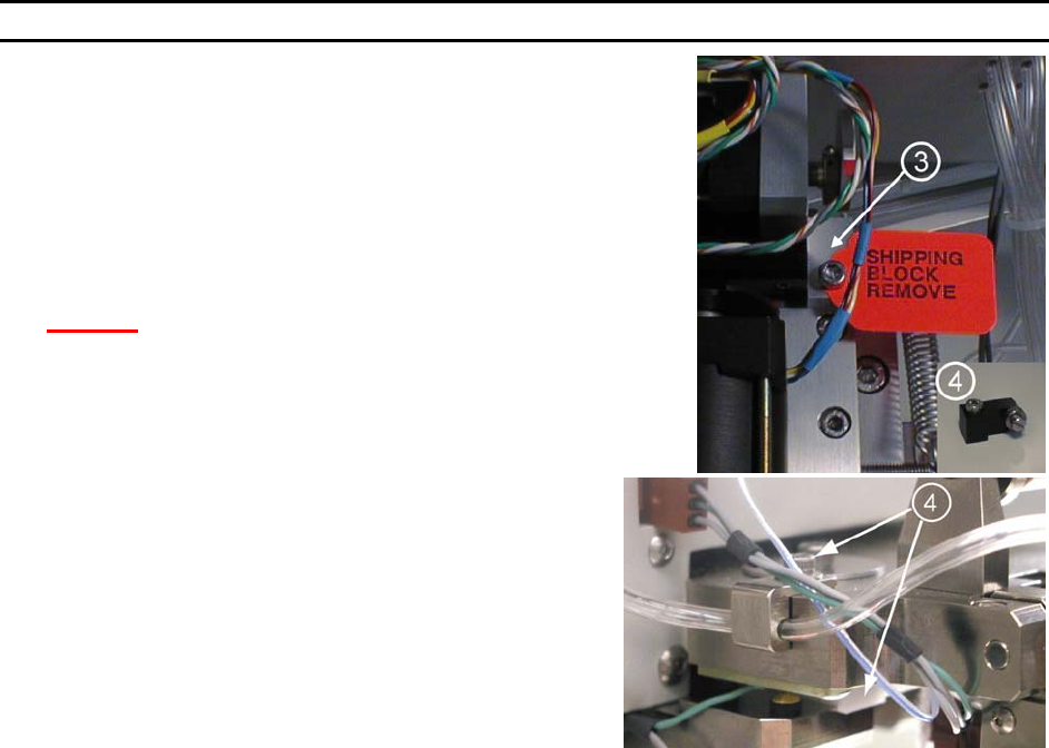
TEP 10
Remove the Firing Switch Shipping Block (P/N 6873.002)
f located
under the tooling head. Remove the cap screw and washer on top
of the tool head. Gently pull the shipping block free, being
careful not to harm the transducer.
Connecting the Accessories
STEP 1 - AIR
Connect ¼” poly-flow tubing from air regulator to rear panel fitting.
Adjust for approximately 50 psi nominal.
S
TEP 2 - MICROSCOPE
Attach the Microscope Mount to the Microscope Support, located in the center of the machine, using the
screw and washer provided. Position the Mount so that it is completely forward, close to the operator.
Attach the Microscope to the Microscope Arm assembly. Adjust the arm to place the Microscope in the
maximum up position. Attach the Illuminator to the Microscope using the adapter which threads into the
Microscope. Position the wire for the Illuminator in the direction of the Microscope Arm Assembly, away
from the operator.
Place the Microscope into the Microscope mount on the machine using caution not to interfere with the
video camera assembly.
After all accessories are connected and the machine is ready to bond, the Microscope needs to be
adjusted and properly centered. (See Thread and Bond-Off Section, page 33).
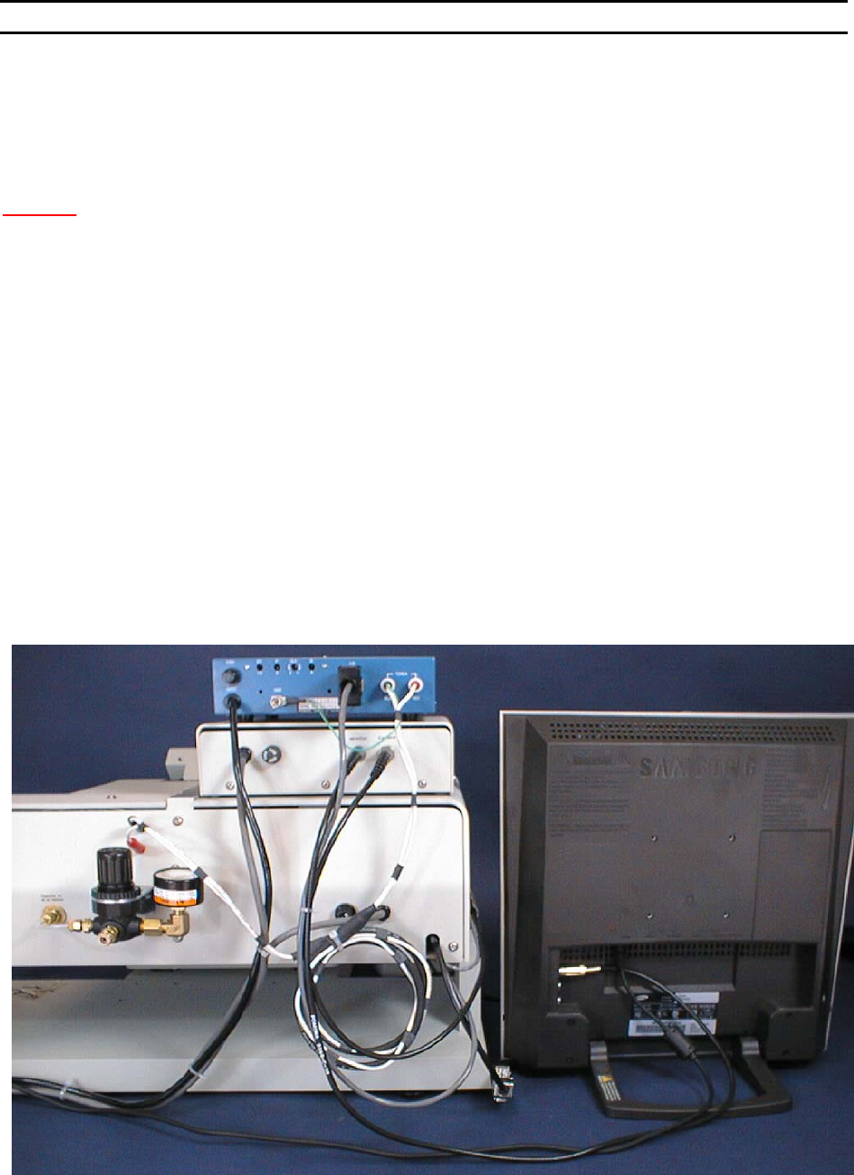
S
TEP 3 - VIDEO CROSSHAIR GENERATOR
Connect the BNC cable from the V
IDEO OUT connector of the Crosshair Generator to the VIDEO IN
connector on the Video Monitor. Plug in both units to 110VAC, 50-60Hz.
WEST•BOND MODEL 454647E SERIES INSTRUCTION MANUAL
13
INSTALLATION
Connecting the Accessories
STEP 4 - CAMERA
Check Camera (Horizontally Mounted). Make sure the Camera Body and Lens Assembly are
perpendicular to X-Y Platform. The Camera is factory set, However it may have been disturbed during
shipping. See page 17 for realignment procedure.
C
AUTION! Never attempt to move or lift machine with the Camera or Camera Mount !!!
Connect the BNC cable from the V
IDEO OUT connector of the camera to the VIDEO IN of the Crosshair
Generator.
S
TEP 5 - KEY PAD
Attach the Key Pad cable to the 9 pin D-Sub connector that exits from the left-rear side of the machine.
S
TEP 6 - NEGATIVE EFO GENERATOR
Set the Generator on top the crosshair generator, ensure the power switch is off and plug into 110VAC.
Locate the cable with the Honda connector coming out of the back of the 454647E and connect it into the
back of the NEFO Generator. Remove the torch cable from its bag and plug into the rear of the NEFO
Generator. Attach the ground to the provided thumb nut. Finally plug the torch cable into the 454647E
paying special attention to ensure that each end of the cable is plugged into its correct color connectors.
(i.e. red to red and black to black)
S
TEP 7** - WORKHOLDER /TEMPERATURE CONTROLLER
Connect the 5-pin Bendix connector of the Workholder to the rear of the Temperature Controller. If the
Workholder has Vacuum, connect the Orange hose from the Workholder to a Vacuum Supply. Plug the
Temperature Controller to 110VAC, 50-60Hz.
** OPTIONAL
WEST•BOND MODEL 454647E SERIES INSTRUCTION MANUAL
14
INSTALLATION
Bond Tool Installation
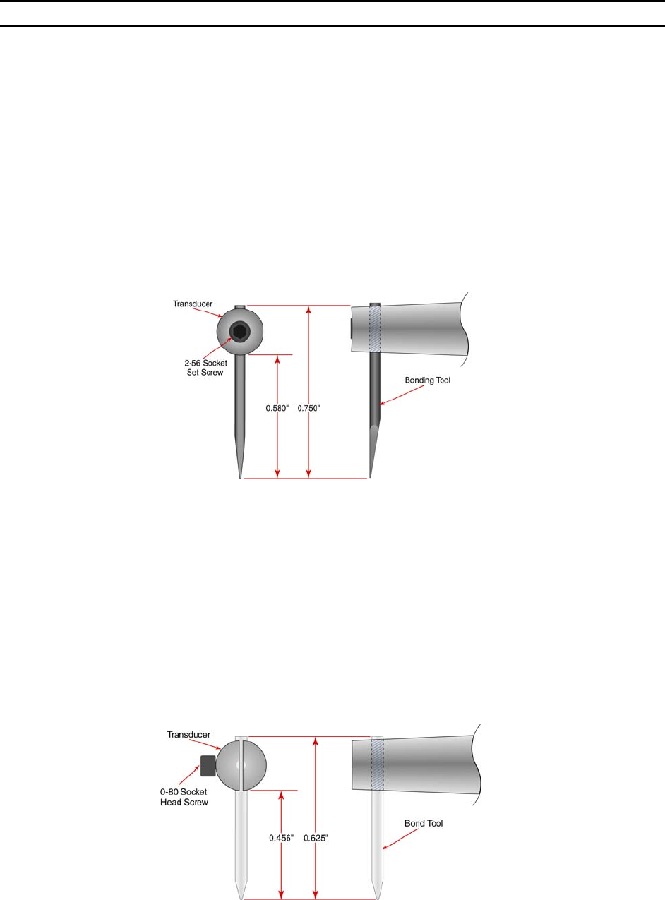
45° AND 90° WEDGE BONDING TOOL
The bonding wedge is a major influence on a successful program. Taking the time to establish the
correct wedge for each specific application will ensure high quality bonding. The 454647E requires that
the shank diameter of the tool be 1/16”. The K~Sine K~24-W transducer used in this wedge-wedge
configuration has been specially developed in conjunction with an 0.750” (19mm) length tool. Different
length tools can be used, however an entirely different setup (with regards to ultrasonic power, ultrasonic
time, and force) will be required.
To install the bonging tool, loosen the transducer set screw and insert the bonding tool through bottom of
transducer. If the machine is in the 4500E mode, it may be helpful to have clamps open when installing
the tool. Positioning the bonding tool according to the drawing below gives the user a good starting
position to begin running the Ultrasonic Positioning Utility (UPU). See page 67 for details on the UPU.
B
ALL BONDING CAPILLARY
Just as the bonding wedge is a major influence to a successful program, so is the ceramic capillary used
for ball bonding. Taking the time to establish the correct wedge for each specific application will ensure
high quality bonding. When in the 4700E mode, the 454647E requires that the shank diameter of the tool
be 1/16”. The K~Sine K~27-EC transducer used in this ball bond configuration has been specially
developed to work with a 0.625” (16mm) length capillary. Different length T
ORCH WANDS can be ordered
to accommodate a variety of capillary lengths, up to 1” (25mm).
To install the bonging tool, loosen the transducer set screw and insert the bonding tool through bottom of
transducer. It may be helpful to have clamps open when positioning tool. Positioning the bonding tool
according to the drawing below gives the user a good starting position to begin running the Ultrasonic
Positioning Utility (UPU). See page 67 for details on the UPU.