wire-bonder.pdf - 第21页
WEST•BOND MODEL 454647E SER IES INSTRUCTION MANUAL 15 INSTALLATION Torch Wand and Tail Setup Ball size is affected by many different factors including Ball Size setting, Tail Lengt h, distance between the tool and the To…
WEST•BOND MODEL 454647E SERIES INSTRUCTION MANUAL
14
INSTALLATION
Bond Tool Installation
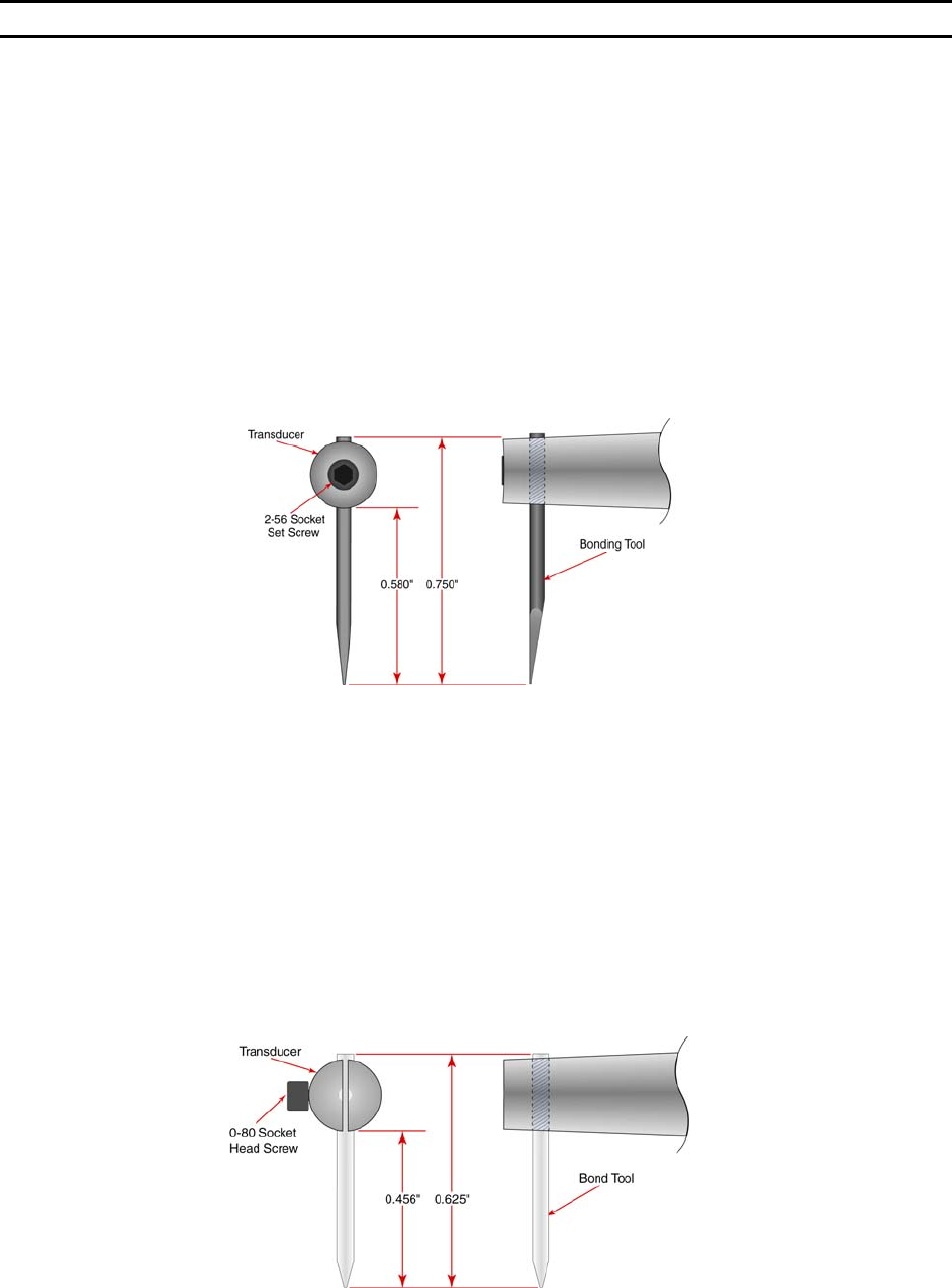
45° AND 90° WEDGE BONDING TOOL
The bonding wedge is a major influence on a successful program. Taking the time to establish the
correct wedge for each specific application will ensure high quality bonding. The 454647E requires that
the shank diameter of the tool be 1/16”. The K~Sine K~24-W transducer used in this wedge-wedge
configuration has been specially developed in conjunction with an 0.750” (19mm) length tool. Different
length tools can be used, however an entirely different setup (with regards to ultrasonic power, ultrasonic
time, and force) will be required.
To install the bonging tool, loosen the transducer set screw and insert the bonding tool through bottom of
transducer. If the machine is in the 4500E mode, it may be helpful to have clamps open when installing
the tool. Positioning the bonding tool according to the drawing below gives the user a good starting
position to begin running the Ultrasonic Positioning Utility (UPU). See page 67 for details on the UPU.
B
ALL BONDING CAPILLARY
Just as the bonding wedge is a major influence to a successful program, so is the ceramic capillary used
for ball bonding. Taking the time to establish the correct wedge for each specific application will ensure
high quality bonding. When in the 4700E mode, the 454647E requires that the shank diameter of the tool
be 1/16”. The K~Sine K~27-EC transducer used in this ball bond configuration has been specially
developed to work with a 0.625” (16mm) length capillary. Different length T
ORCH WANDS can be ordered
to accommodate a variety of capillary lengths, up to 1” (25mm).
To install the bonging tool, loosen the transducer set screw and insert the bonding tool through bottom of
transducer. It may be helpful to have clamps open when positioning tool. Positioning the bonding tool
according to the drawing below gives the user a good starting position to begin running the Ultrasonic
Positioning Utility (UPU). See page 67 for details on the UPU.
WEST•BOND MODEL 454647E SERIES INSTRUCTION MANUAL
15
INSTALLATION
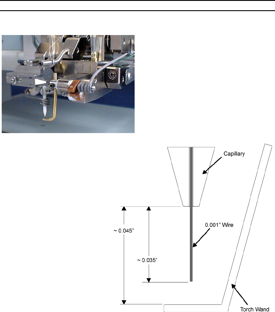
Torch Wand and Tail Setup
Ball size is affected by many different factors
including Ball Size setting, Tail Length, distance
between the tool and the Torch Wand, wire
diameter, wire elongation, wire quality (age), and
Torch Wand cleanliness. When all settings are
optimized (per application), the ball will form just
below the tip of the capillary and the machine will
pull the ball up into the pocket on the bottom of the
tool in preparation of the next bond. If the tail length
is too short, the Tool to Torch distance is too short,
or the ball size setting is turned up too high, the ball
will form up inside the capillary. This causes
deformed balls and also shortens the life of the
ceramic tool.
This drawing represents the recommended setup for
0.001” gold wire. These numbers are approximations
and may vary for different applications.
R
ECOMMENDED SETTINGS
Wire Size: 0.001”
Tail Length: ~0.035”
Tool to Torch: ~0.045”
Wire Gap: ~0.010”
WEST•BOND MODEL 454647E SERIES INSTRUCTION MANUAL
16
INSTALLATION
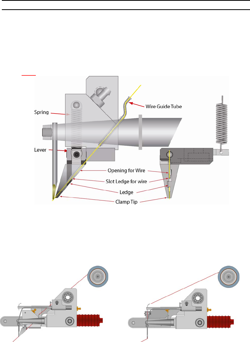
Installing the Bonding Wire
The 454647E is equipped with a standard ½” Ball Bearing Spool Mount. Slide the ½” spool over the
Spool Mount such that the wire de-spools over the top (counter-clockwise when viewed from the right
side). Carefully route the wire through guides, transducer, clamps and bonding tool. With the 45° Bonding
head, the wire runs through guide tube, which runs through the transducer. From the home menu, press 6
on the keypad to manually open and thread the clamp blades making sure that the clamps fully capture
the wire.
N
OTE! The wire needs to be above the wire guide in the back side of clamp blades.
The guide tube for the 90° has a single bend for adding a slight drag to the wire. Because of these
bends, it is necessary to “inch” the wire through by holding the tweezers close to the Guide Tube. When
the wire is visible below the Guide Tube, pull the wire through. Turn on the machine power. Press the “6”
key, for T
HREAD and BOND-OFF mode, to open the Clamp Blades. (Air must be connected and active as
the clamp open and close functions are operated by air.) Thread the wire through the Clamp Blades, then
through the Bonding Tool. To Close or Open the Clamp Blades, press the “6” Key, or to feed more wire
through the tool, Press the “A” key, (For more information on threading the tool see page 33.) The
bonding wire should be positioned according to the drawings below.