wire-bonder.pdf - 第22页
WEST•BOND MODEL 454647E SER IES INSTRUCTION MANUAL 16 INSTALLATION Installing the Bonding Wire The 454647E is equipped with a standard ½ ” Ball Bearing Spool Mount. Slide the ½” spool over the Spool Mount such that th e …
WEST•BOND MODEL 454647E SERIES INSTRUCTION MANUAL
15
INSTALLATION
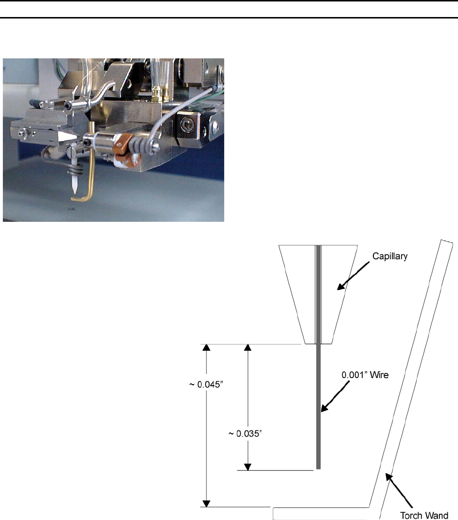
Torch Wand and Tail Setup
Ball size is affected by many different factors
including Ball Size setting, Tail Length, distance
between the tool and the Torch Wand, wire
diameter, wire elongation, wire quality (age), and
Torch Wand cleanliness. When all settings are
optimized (per application), the ball will form just
below the tip of the capillary and the machine will
pull the ball up into the pocket on the bottom of the
tool in preparation of the next bond. If the tail length
is too short, the Tool to Torch distance is too short,
or the ball size setting is turned up too high, the ball
will form up inside the capillary. This causes
deformed balls and also shortens the life of the
ceramic tool.
This drawing represents the recommended setup for
0.001” gold wire. These numbers are approximations
and may vary for different applications.
R
ECOMMENDED SETTINGS
Wire Size: 0.001”
Tail Length: ~0.035”
Tool to Torch: ~0.045”
Wire Gap: ~0.010”
WEST•BOND MODEL 454647E SERIES INSTRUCTION MANUAL
16
INSTALLATION
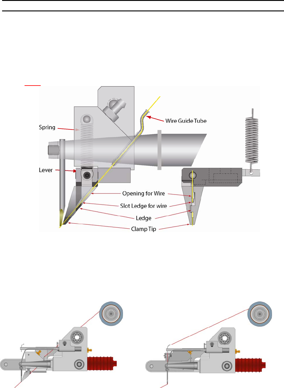
Installing the Bonding Wire
The 454647E is equipped with a standard ½” Ball Bearing Spool Mount. Slide the ½” spool over the
Spool Mount such that the wire de-spools over the top (counter-clockwise when viewed from the right
side). Carefully route the wire through guides, transducer, clamps and bonding tool. With the 45° Bonding
head, the wire runs through guide tube, which runs through the transducer. From the home menu, press 6
on the keypad to manually open and thread the clamp blades making sure that the clamps fully capture
the wire.
N
OTE! The wire needs to be above the wire guide in the back side of clamp blades.
The guide tube for the 90° has a single bend for adding a slight drag to the wire. Because of these
bends, it is necessary to “inch” the wire through by holding the tweezers close to the Guide Tube. When
the wire is visible below the Guide Tube, pull the wire through. Turn on the machine power. Press the “6”
key, for T
HREAD and BOND-OFF mode, to open the Clamp Blades. (Air must be connected and active as
the clamp open and close functions are operated by air.) Thread the wire through the Clamp Blades, then
through the Bonding Tool. To Close or Open the Clamp Blades, press the “6” Key, or to feed more wire
through the tool, Press the “A” key, (For more information on threading the tool see page 33.) The
bonding wire should be positioned according to the drawings below.
WEST•BOND MODEL 454647E SERIES INSTRUCTION MANUAL
17
INSTALLATION
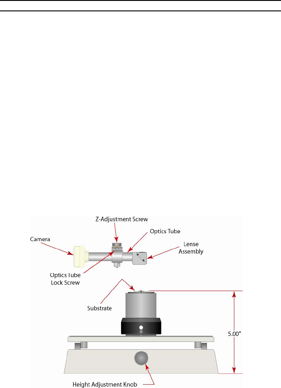
Adjusting the Camera Focus
The camera focus is set at the factory before shipment. Unfortunately, the bumping and jarring that the
machine encounters during shipment may upset this delicate adjustment. A slight adjustment may be
required to bring the camera back into factory specifications. Below you will find a detailed set of
instructions to effect this adjustment. W
EST•BOND recommends reading all of the steps prior to attempting
any adjustment. This is to familiarize the operator with the camera configuration, allowing for a quicker
and more effective adjustment process. If you encounter any difficulties or have any questions, feel free
to contact W
EST•BOND or your local factory representative technical support for help.
S
TEP 1 - SETTING THE WORK HEIGHT
Place the package (a.k.a. the part to be bonded) upon its workholder and refer to page 28 to correctly set
the W
ORK HEIGHT. When this is properly set, there will be a 5 inch differential between the bottom edge of
the platform and the top of the bonding surface.
S
TEP 2 – INCH DOWN AND BOND OFF
From the home menu (A
LIGN BOND MENU) press key 6 to go to the THREAD AND BOND menu. Using the G
key, look into the microscope, inch down onto your work surface, and bond off. In this mode all of the
machine’s brakes will lock in order to keep the bonding surface underneath the camera eye.
S
TEP 3 – ADJUSTING CAMERA HEIGHT
Loosen the Thumb Nut
1
/
4
to
1
/
2
of a turn. This nut simply locks up the camera adjustment and it is not
necessary to loosen it excessively. Located in the top of the adjustment block, above the T
HUMB NUT is
the CAMERA Z-ADJUSTMENT SCREW. Insert a
1
/
8
” Allen wrench and turn slowly while observing the bonding
surface in the monitor. Turning this screw clockwise will raise the camera assembly while counter-
clockwise will lower it. Once the optimum focus is achieved, lock down the thumb nut and press the A
key. Bond off again and set the crosshairs.