wire-bonder.pdf - 第29页
WEST•BOND MODEL 454647E SER IES INSTRUCTION MANUAL 23 OPERATION The 454647E Semi-Automatic Wi re Bonder has been specifically designed to be versatile, depe ndable, and easy to use. To effect t his end, the following sec…
WEST•BOND MODEL 454647E SERIES INSTRUCTION MANUAL
22
MACHINE CONTROLS
Negative Electronic Flame Off
POWER SWITCH
The power switch turns the power on to the NEFO unit. Always turn this unit off when servicing the torch
or head assembly.
P
OWER DIAL
Sets the Ball Forming Current to a constant. The voltage will vary to keep the power the same to
consistently make the same size ball each time. The power dial will set the current from 7.5ma – 25ma.
The current setting can be adjusted to a 9ma – 35.5ma range for larger balls on 1.5 – 2.0 mil wire.
Jumper E1 on the mother board (Lower PCB) should be changed from pins 1-2 to 2-3 for the high power
setting.
T
IME DIAL
Ball Forming Time, or a cut-
off time for ball formation.
Forming time is set between
2.1ms to a maximum of
10ms. Factory setting of the
time is at 2.5 (approximately
4ms), this is the optimum
setting.
LED’
S
The Open and Short LED’s
are for designation of a ball
fault. If the Open LED is lit,
then the gap between the
end of the wire and the torch
tip is too large for ball
formation. If the Short LED is
lit, then the wire has
contacted the torch tip
causing a short where no
spark is formed.
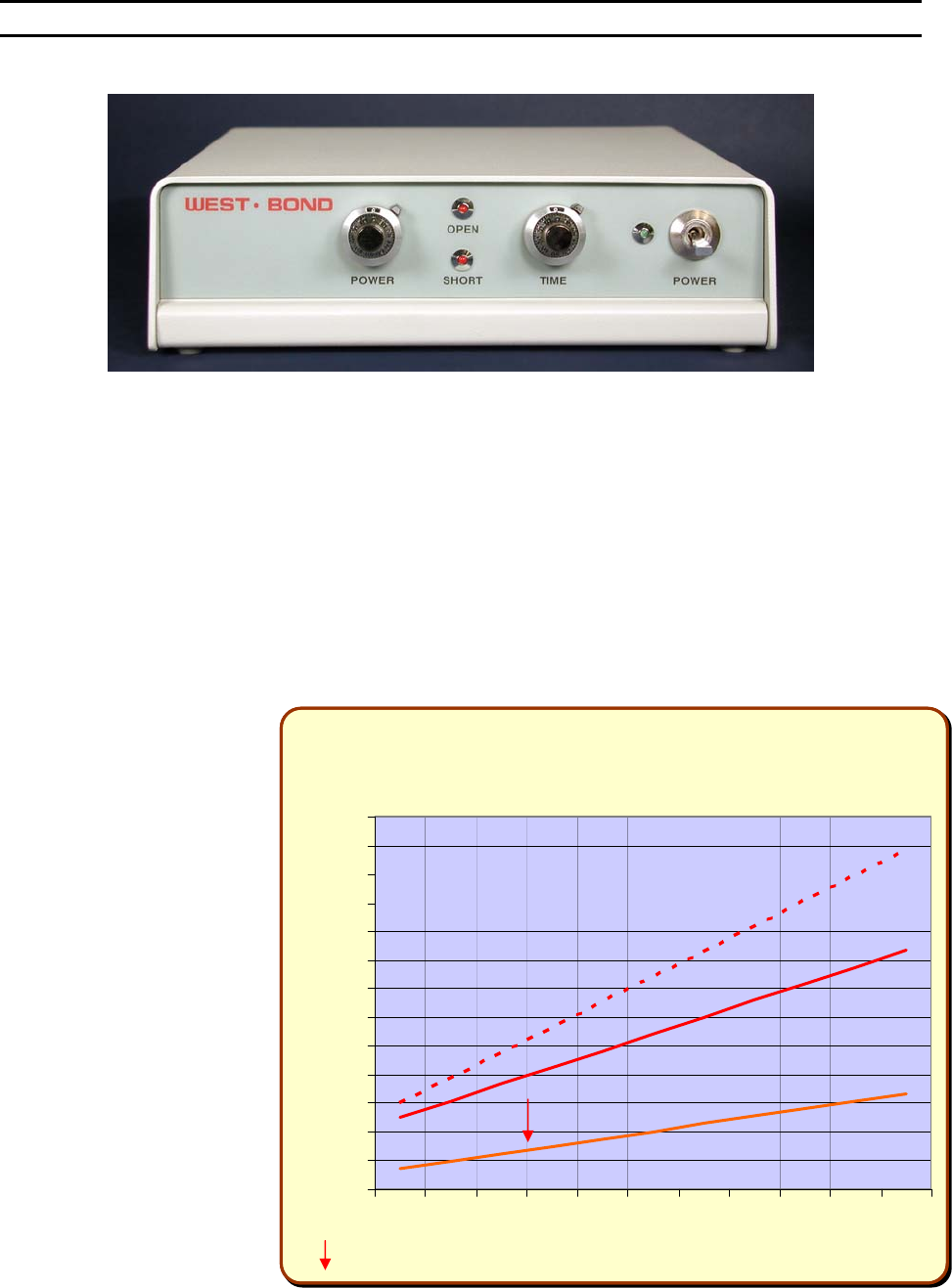
NEFO
Power & Time Settings
0
3
6
9
12
15
18
21
24
27
30
33
36
39
012345678910
Dial Setting
Current (ma) / Time (ms)
-Factor
y
Settin
g

WEST•BOND MODEL 454647E SERIES INSTRUCTION MANUAL
23
OPERATION
The 454647E Semi-Automatic Wire Bonder has been specifically designed to be versatile, dependable,
and easy to use. To effect this end, the following sections have been developed to help the operator take
advantage of its advanced bonding features. A in-depth study and understanding of this section will result
in better bonds, higher gram pulls, and faster set up times.
Wire Bonding
The process of wire bonding with WEST•BOND’S 454647E is rather straight forward. The micromanipulator
control, positioned to the right of the work platform, is linked to the tool head and camera assemblies
through an 8:1 ratio. This mechanical link allows the operator to accomplish extremely precise and fine
adjustments to the tool head and camera assemblies.
To create the first wire bond, simply use the micromanipulator to position the monitor’s crosshairs over
the critical bond and press the G key, the manipulator G
O BUTTON, or the 0 key. Below is a list of 4
different machine modes that correspond to the keys listed above.
F
ULL-AUTO MODE
Once this mode is selected and the G key or G
O BUTTON is pressed, the bonding sequence will
continue without operator intervention until the completion of one entire wire run. In this mode the
operator may stop the bonding at anytime by pressing and holding any key. For selection details
and more information regarding this mode see page 29.
H
ALF-AUTO MODE
The operator is required to press the G key, or the G
O BUTTON, each time the machine
approaches the work to make a bond. This mode allows the operator to manually select a
bonding point by using the micromanipulator to position the tool prior to contact. The bonding
sequence of this mode is described as follows: At first bond, the tool will stop at search if the “G”
key is pressed and held, allowing XY movement, and the bonding sequence will continue upon
release of the “G” key. For selection details and more information regarding this mode see page
30.
M
ANUAL MODE
This mode allows the operator to slowly lower the Tooling Head by pressing the 0 key until the
Bonding Tool gently touches the bond surface. At anytime the operator can manually select a
bonding point by using the micromanipulator to position the tool prior to contact. If it is necessary
to raise the already lowered bond tool, the operator can press the 5 key to raise the Tooling
Head. For more information regarding this mode see page 32.
Z-L
EVER MANUAL MODE
By using the Z-axis control arm, the operator can slowly inch down to the first S
EARCH ELEVATION.
The operator can take over with the keypad or Go button at any time.
WEST•BOND MODEL 454647E SERIES INSTRUCTION MANUAL
24
OPERATION
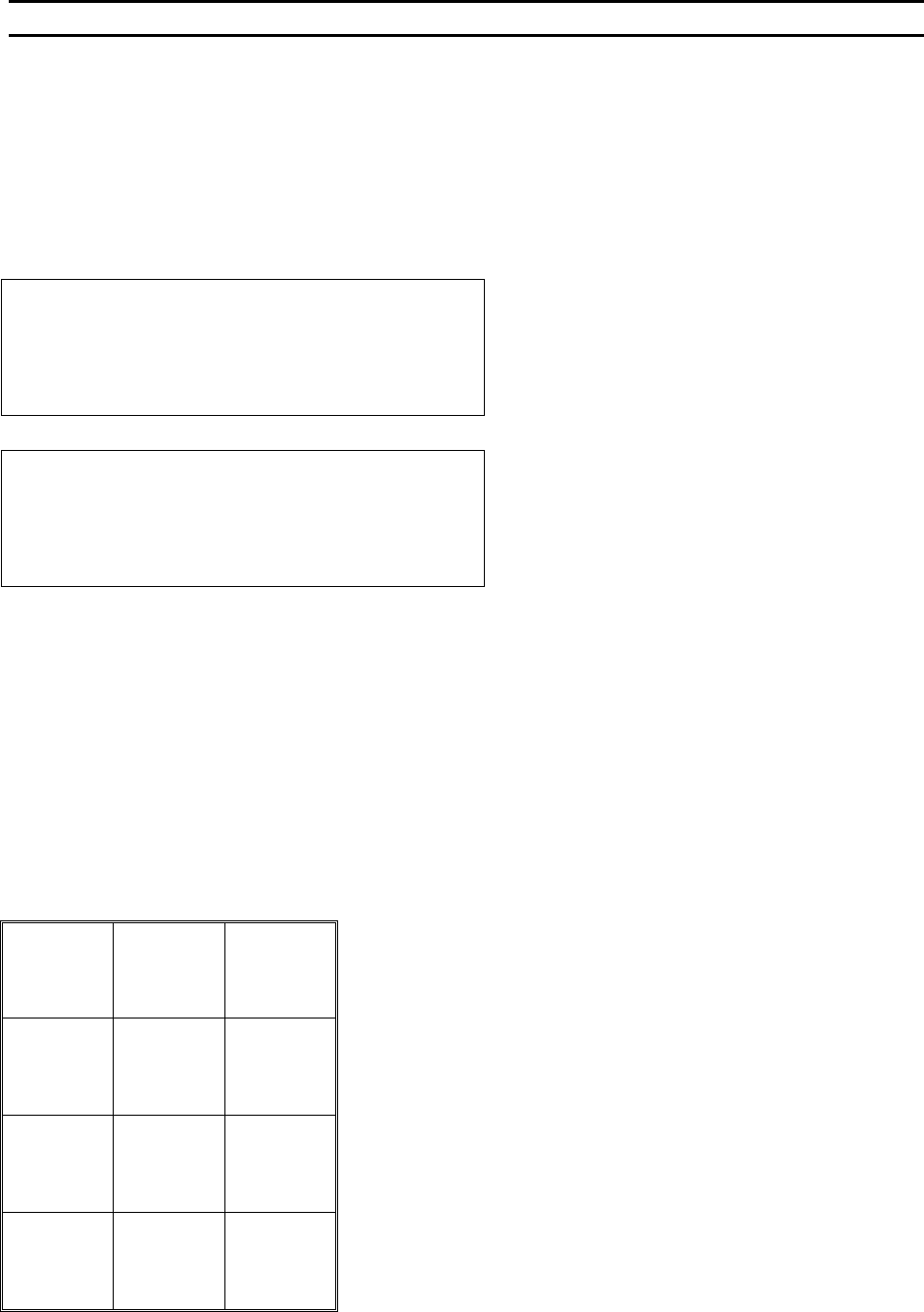
Align Menu or “Home” Menu
The following messages are displayed by the 454647E during operation. The rectangles on the left
represent the LCD and examples of its contents. The key format at the bottom of the page indicates the
key functions available when viewing the screen described.
ALIGN MENU 1 for alignment of the critical bond of any given bond sequence. (This is the default mode,
also called “Home” Menu.
D
ISPLAY IN 4500E AND 4600E MODES
ALIGN BOND 1 of 5 USE MICROSCOPE.
Device 1, Type 2, Wire 1
7=Lock X 8=More options 9=Monitor
A=Feed 0=Manual bond G=Full-Auto
DISPLAY IN 4700E MODE
ALIGN BOND 1 of 5 USE MICROSCOPE.
Device 1, Type 2, Wire 1
7=Lock X 8=More options 9=Monitor
A=Torch 0=Manual bond G=Full-Auto
Key Format:
1
Go To
Device/Type
2
Home
3
Edit
4
Info
5
Thread
Or
Bond-off 6
Lock / Move
X Axis
7
More
Options
8
Microscope /
Monitor
9
Feed
A
Manual
Bond
0
Half-
Or
Full-Auto G