wire-bonder.pdf - 第49页
WEST•BOND MODEL 454647E SER IES INSTRUCTION MANUAL 43 Type 2 Typ e 1 PROGRAMMING User Data Settings Wire T YPE E DIT M ENU is designed to the following tasks: 1. E DIT T YPE – page 73 a. E DIT N UMBER OF W IRES – page 74…

WEST•BOND MODEL 454647E SERIES INSTRUCTION MANUAL
42
PROGRAMMING
The following pages demonstrate the expected displays and programmable options of the 454647E. The
programmable features are broken into two sections: One section is called M
ACHINE SETTINGS and the
other is called U
SER DATA SETTINGS.
Machine Settings
These are items generally used for initial machine set-up and are infrequently changed. Options in this
section may require some modification if the application changes significantly. Here are the options
available for programming in this section:
1. C
LAMP HOME – page 54
2. W
IRE PULL – page 55
3. W
IRE TAIL – page 56
4. B
ALL FAULT – page 57
5. D
UAL FORCE – page 58
6. F
ORCE ADJUST – page 59
7. R
ESTART HEIGHT – page 61
8. L
IFT-TO-PULL – page 62
9. U
LTRASONIC POWER DURING FEED – page 63
10. U
LTRASONIC POWER DURING THREAD – page 64
11. U
LTRASONIC DIAGNOSTIC TEST – page 65
User Data Settings
These are options commonly used by the operator. For this reason they have been separated from the
M
ACHINE SETTINGS and stored into DEVICES, WIRE TYPES, or BONDS. Each device allows one or more wire
types. Each wire type allows one or more bonds. Here are the options available for programming in this
section:
1. D
EVICE EDIT – page 68
2. W
IRE TYPE EDIT – page 71
3. B
OND EDIT – page 79
The D
EVICE EDIT MENU is designed to do the following tasks:
a. C
OPY DEVICE – page 70
b. E
RASE DEVICE – page 69
WEST•BOND MODEL 454647E SERIES INSTRUCTION MANUAL
43
Type 2
Type 1
PROGRAMMING
User Data Settings
Wire TYPE EDIT MENU is designed to the following tasks:
1. E
DIT TYPE – page 73
a. E
DIT NUMBER OF WIRES – page 74
b. L
OOP EDIT – page 88
c. E
DIT CRITICAL BOND – page 75
2. A
DD TYPE – page 76
3. C
OPY TYPE – page 77
4. D
ELETE TYPE – page 72
The B
OND EDIT MENU is designed to do the following tasks:
1. E
DIT BOND – page 79
a. E
DIT ULTRASONIC POWER – page 80
b. E
DIT ULTRASONIC TIME – page 81
c. E
DIT BOND FORCE – page 82
d. E
DIT BOND DEPTH – page 83
e. E
DIT INHIBIT AUTO-MODE – page 84
f. E
DIT SPEED – page 85
g. E
DIT PRE-BOND DELAY – page 86
2. E
DIT NUMBER OF BONDS - page 87
Wire Types
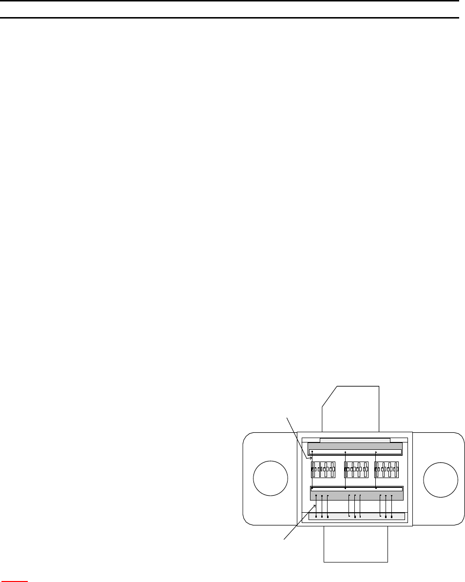
EXAMPLE OF A DEVICE
The diagram to the right shows an
example of a device, which has two wire
types. Where the number of wires for
Type 1 is 9 with 2 bonds each wire, and
the number of wire for Type 2 is 3 with 3
bonds for each wire.
N
OTE: When Ball Bonding (Ball-Wedge), there should be a maximum of 2 bonds per wire, as a capillary
can not guild the wire through a second loop.
WEST•BOND MODEL 454647E SERIES INSTRUCTION MANUAL
44
PROGRAMMING
Learn to Setup Device
This option is designed to take the operator through an simple part setup. Other, more advanced
parameters may need to be adjusted for optimum bonding results, but this quick setup will cover all of the
basics.
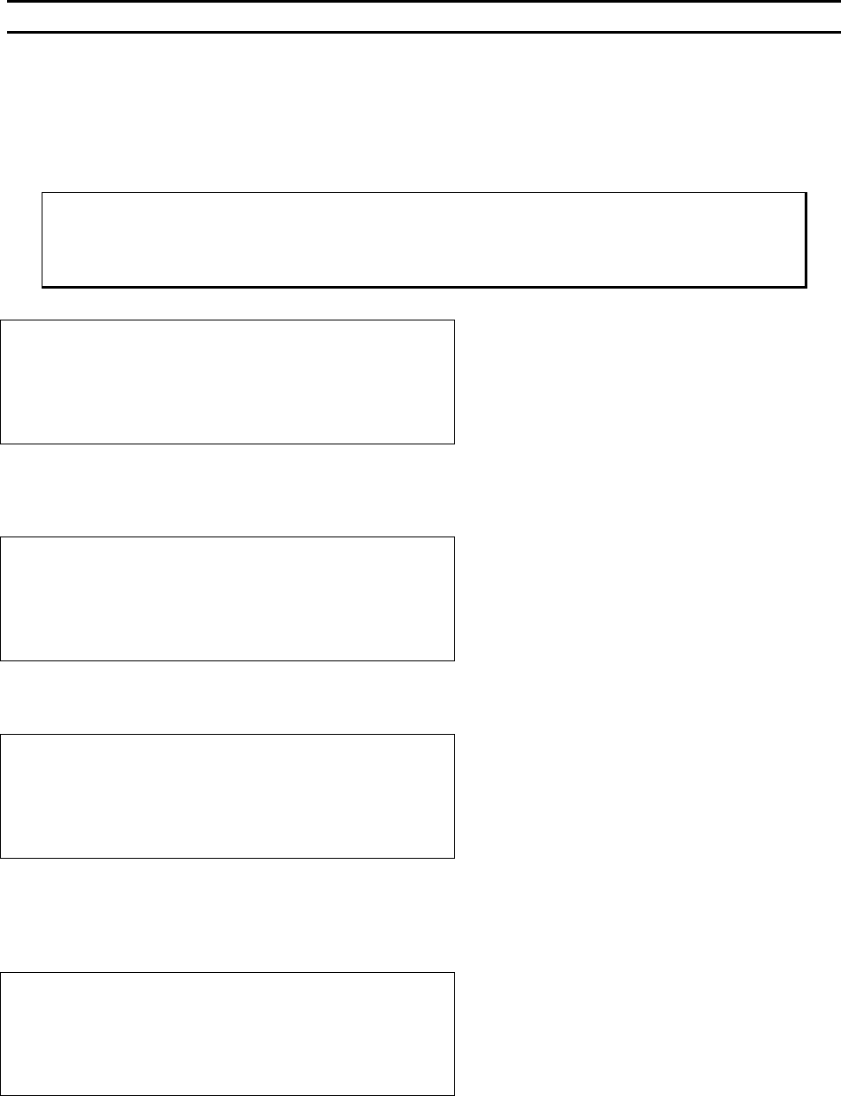
ϑ To call “Learn to Setup Device”
From the H
OME menu press 4 (EDIT) and then press G (LEARN MODE).
LEARN TO SETUP DEVICE 1:
5=Go To
7=Prev device 8=Device 1 9=Next device
A=Prev menu G=OK
Æ
PRESS KEY G
Å
This menu is the only place where the name of the Device can be set or changed and it can only be
accessed through this L
EARN MODE.
EDIT NAME OF DEVICE 1: _
4=”A” 5=Increase 6=”Z”
7=Left 8=”_” 9=Right
A=Prev option 0=Decrease G=OK
Æ
PRESS KEY G
Å
See page 43 for a description of W
IRE TYPES.
DEVICE 1: HOW MANY WIRE TYPES? 1
4=Key in 5=Increase
A=Prev option 0=Decrease G=OK
Æ
PRESS KEY G
Å
Here the operator is asked to specify the number of wires desired in each W
IRE TYPE. This menu will
repeat itself - one time for each wire type specified (i.e. if 6 was entered in the previous menu, the
machine will ask for the number of wires required in each type by repeating this menu 6 times).
HOW MANY WIRES FOR TYPE 1? 0
(0 wire means repeat this type forever.)
4=Key in 5=Increase
A=Prev option 0=Decrease G=OK
Æ
PRESS KEY G
Å