wire-bonder.pdf - 第50页
WEST•BOND MODEL 454647E SER IES INSTRUCTION MANUAL 44 PROGRAMMING Learn to Setup Device This option is designe d to take the operator thr ough a n simple part setup. Other, more adva nced parameters may need to be adjust…
WEST•BOND MODEL 454647E SERIES INSTRUCTION MANUAL
43
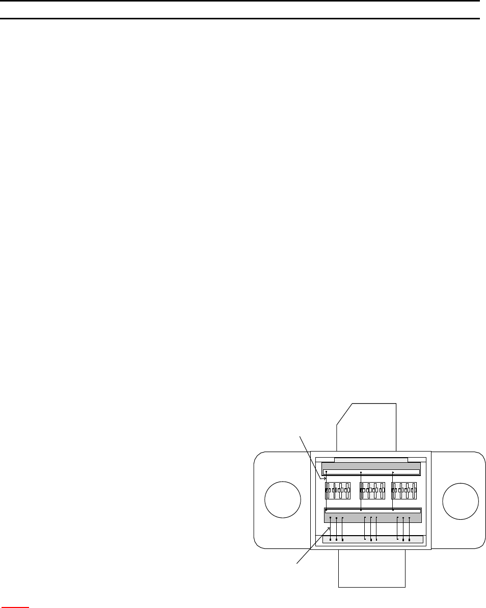
Type 2
Type 1
PROGRAMMING
User Data Settings
Wire TYPE EDIT MENU is designed to the following tasks:
1. E
DIT TYPE – page 73
a. E
DIT NUMBER OF WIRES – page 74
b. L
OOP EDIT – page 88
c. E
DIT CRITICAL BOND – page 75
2. A
DD TYPE – page 76
3. C
OPY TYPE – page 77
4. D
ELETE TYPE – page 72
The B
OND EDIT MENU is designed to do the following tasks:
1. E
DIT BOND – page 79
a. E
DIT ULTRASONIC POWER – page 80
b. E
DIT ULTRASONIC TIME – page 81
c. E
DIT BOND FORCE – page 82
d. E
DIT BOND DEPTH – page 83
e. E
DIT INHIBIT AUTO-MODE – page 84
f. E
DIT SPEED – page 85
g. E
DIT PRE-BOND DELAY – page 86
2. E
DIT NUMBER OF BONDS - page 87
Wire Types
EXAMPLE OF A DEVICE
The diagram to the right shows an
example of a device, which has two wire
types. Where the number of wires for
Type 1 is 9 with 2 bonds each wire, and
the number of wire for Type 2 is 3 with 3
bonds for each wire.
N
OTE: When Ball Bonding (Ball-Wedge), there should be a maximum of 2 bonds per wire, as a capillary
can not guild the wire through a second loop.
WEST•BOND MODEL 454647E SERIES INSTRUCTION MANUAL
44
PROGRAMMING
Learn to Setup Device
This option is designed to take the operator through an simple part setup. Other, more advanced
parameters may need to be adjusted for optimum bonding results, but this quick setup will cover all of the
basics.
ϑ To call “Learn to Setup Device”
From the H
OME menu press 4 (EDIT) and then press G (LEARN MODE).
LEARN TO SETUP DEVICE 1:
5=Go To
7=Prev device 8=Device 1 9=Next device
A=Prev menu G=OK
Æ
PRESS KEY G
Å
This menu is the only place where the name of the Device can be set or changed and it can only be
accessed through this L
EARN MODE.
EDIT NAME OF DEVICE 1: _
4=”A” 5=Increase 6=”Z”
7=Left 8=”_” 9=Right
A=Prev option 0=Decrease G=OK
Æ
PRESS KEY G
Å
See page 43 for a description of W
IRE TYPES.
DEVICE 1: HOW MANY WIRE TYPES? 1
4=Key in 5=Increase
A=Prev option 0=Decrease G=OK
Æ
PRESS KEY G
Å
Here the operator is asked to specify the number of wires desired in each W
IRE TYPE. This menu will
repeat itself - one time for each wire type specified (i.e. if 6 was entered in the previous menu, the
machine will ask for the number of wires required in each type by repeating this menu 6 times).
HOW MANY WIRES FOR TYPE 1? 0
(0 wire means repeat this type forever.)
4=Key in 5=Increase
A=Prev option 0=Decrease G=OK
Æ
PRESS KEY G
Å

WEST•BOND MODEL 454647E SERIES INSTRUCTION MANUAL
45
PROGRAMMING
Learn to Setup Device
In this menu the operator is asked to specify the number of bonds for each WIRE TYPE. Two bonds equal
one loop, three bonds will create two loops, and so on. As with the afore mentioned menu, this menu will
repeat itself - one time for each wire type specified.
HOW MANY BONDS FOR TYPE 1? 2
4=Key in 5=Increase
7=Prev type 8=Type 1 9=Next type
A=Prev option 0=Decrease G=OK
Æ
PRESS KEY G
Å
The critical bond is typically the bond to be placed upon the smallest pad or the most difficult pad to
target. The C
RITICAL BOND setting does not set which bond goes first. For example: a wire type with three
bonds per wire (2 loops) may have the second bond (the middle bond) set as the critical bond. This would
allow the operator to target the center pad immediately prior to bonding. Therefore, the machine would
place the first and third bonds in direct relation to this second critical bond pad. This menu will also
repeat itself - one time for each wire type specified.
CRITICAL BOND FOR TYPE 1 is Bond 1
7=Prev bond 8=Bond 1 9=Next bond
A=Prev option G=OK
Æ
PRESS KEY G
Å
The machine will now step the operator through a sequence designed to set up the desired loop shape.
ABOUT TO EDIT LOOP MOTION for Type 1
-> Use manipulator to align TV crosshair
to Bond 1 and press G when ready
A=Prev option
Æ
PRESS KEY G
Å
Depending upon the model mode the machine is in you may or may not see this menu.
EDIT LOOP MOTION
Device 1 Type 1: (2 Bonds)
-> LOOK IN MICROSCOPE,
SELECT BOND 1 AND PRESS G WHEN READY.
Æ
PRESS KEY G
Å