wire-bonder.pdf - 第6页
WEST•BOND MODEL 454647E SER IES INSTRUCTION MANUAL Rev: 6 January, 2012 vi TROUBLESHOOTING ................................................................................................................ .9 9 Poor Bond Q…
WEST•BOND MODEL 454647E SERIES INSTRUCTION MANUAL
Rev: 6 January, 2012 v
Ultrasonic Power During Feed........................................................................................63
Ultrasonic Power During Thread.....................................................................................64
Ultrasonic Diagnostic Test ..............................................................................................65
Wire Break Z Offset.........................................................................................................66
Ultrasonic Positioning Utility (UPU).................................................................................67
Device Edit Menu............................................................................................................68
Erase Device...................................................................................................................69
Copy Device....................................................................................................................70
Wire Type Edit Menu.......................................................................................................71
Delete Type.....................................................................................................................72
Edit Type.........................................................................................................................73
Edit Number of Wires......................................................................................................74
Edit Critical Bond.............................................................................................................75
Add Type.........................................................................................................................76
Copy Type.......................................................................................................................77
Bond Edit Menu...............................................................................................................78
Edit Bond.........................................................................................................................79
Edit Ultrasonic Power......................................................................................................80
Edit Ultrasonic Time........................................................................................................81
Edit Bond Force ..............................................................................................................82
Edit Bond Depth..............................................................................................................83
Edit Inhibit Auto Mode.....................................................................................................84
Edit Speed.......................................................................................................................85
Edit Pre-Bond Delay........................................................................................................86
Edit Number of Bonds.....................................................................................................87
Edit Loop Motion.............................................................................................................88
Edit Loop Menu...............................................................................................................89
Search.............................................................................................................................90
Z-Before-Y.......................................................................................................................91
Backbend........................................................................................................................92
Loop Elevation ................................................................................................................93
Y-Offset...........................................................................................................................94
Close Clamp at Loop Height...........................................................................................95
Close Clamp at Search...................................................................................................96
ADVANCED PROGRAMMING....................................................................................................97
Loop Pull.........................................................................................................................97
Nudge Up........................................................................................................................98
WEST•BOND MODEL 454647E SERIES INSTRUCTION MANUAL
Rev: 6 January, 2012 vi
TROUBLESHOOTING.................................................................................................................99
Poor Bond Quality...........................................................................................................99
Inconsistent Looping.......................................................................................................100
Ultrasonic Board (P/N A-10345) .....................................................................................101
TOOL HEAD CONVERSION.......................................................................................................102
45° to 90° Tool Head Conversion ...................................................................................102
90° to 45° Tool Head Conversion ...................................................................................103
Wedge to Ball Bonder Tool Head Conversion................................................................104
Change Model Number of Machine................................................................................105
CLAMP ADJUSTMENT................................................................................................................106
Vertical Positioning..........................................................................................................106
Horizontal Positioning .....................................................................................................106
Testing ............................................................................................................................106
RADIANT HEATER CHARTS......................................................................................................107
Dial Settings for 0.750” Tools..........................................................................................107
Dial Settings for 0.625” Tools..........................................................................................108
APPLICATION AND BOND SCHEDULE.....................................................................................109
WARRANTY.................................................................................................................................111
Patent Information...........................................................................................................111
SPARE PARTS............................................................................................................................112
TECHNICAL INFORMATION.......................................................................................................114
PCB’s and Power Supplies.............................................................................................114
Motor Drivers...................................................................................................................115
AC to DC Converter........................................................................................................115
DC to DC Converter........................................................................................................116
Solenoids ........................................................................................................................117
Motor Driver Boards........................................................................................................117
X-Y-Z Head Assembly.....................................................................................................118
Ultrasonic Power Supply.................................................................................................119
SCHEMATIC INFORMATION......................................................................................................120
WEST•BOND MODEL 454647E SERIES INSTRUCTION MANUAL
1
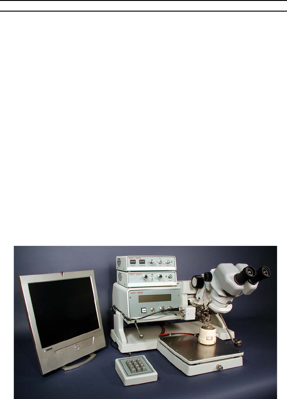
INTRODUCTION
WEST•BOND’S new “E” Version starts the twentieth year of the Model 4500 tradition. This machine was
revolutionary at its inception as the first to make a wire bond connection fully under programmable
software control executed digitally by motors, thus making possible the manufacture of high frequency,
high power semiconductor devices where connections must be identical. The original design, with digi-
switches for input and with LED’s to display individual data lines by binary value, remained unchanged by
customer insistence until finally supplanted by the current 4500 Model of the “B” Series. Now, Model
454647E brings forward the new advances of the “E” Series, notably the placement of all machine
mechanism above the work plane to allow unlimited access, and the setting of axis brakes to lock on
target. In this model the tool, rather than the work, is moved, both for alignment and for bonding, with the
work pre-rotated. There is choice of alignment by either microscope or video. Bond heads are built
around a 63 kHz ultrasonic transducer and provide full three-way convertibility.
When operating in the 4500E mode, the 454647E is an ultrasonic wedge-wedge wire bonder designed to
interconnect wire leads to semi-conductor, hybrid, or microwave devices. The machine bonds aluminum
or gold wires ranging from 0.0007 in. to 0.002 in. Bonds are by the wedge-wedge technique using
ultrasonic energy to attach aluminum wire at room temperature and adding work piece heat for gold wire.
Wire is clamped and threaded diagonally under the bonding wedge, allowing independent feeding action
but requiring front-to-back bonding direction.
When operating in the 4600E mode, the 454647E is a thermosonic wedge-wedge wire bonder designed
to interconnect wire leads to semiconductor, hybrid, or microwave devices. The machine bonds aluminum
or gold wires ranging from 0.0007 in. to 0.002 in. and aluminum or gold ribbon ranging from 0.0005 in. x
0.002 in. to 0.001 in. x 0.01 in. Bonds are made by the wedge-wedge technique using ultrasonic energy
and work piece heat. Wire is clamped and threaded vertically through a hollow wedge, allowing
independent feeding action but requiring front-to-back bonding direction.
When operating in the 4700E mode, the 454647E is a thermosonic ball-wedge wire bonder designed to
interconnect wire leads to semiconductor, hybrid, or microwave devices. The machine bonds gold wires
ranging from 0.0007 in. to 0.002 in. Bonds are made by the ball-to-wedge technique using ultrasonic
energy and work piece heat. Wire is clamped and threaded vertically through a hollow capillary, allowing
independent feeding action. The connection is begun with a ball formed on the end of the wire stock by
electric discharge, and completed by a wedge bond under the end of the capillary tool. The bonding tool
is guided manually by the operator using hand/eye reference to bond targets and elevations.