wire-bonder.pdf - 第60页
WEST•BOND MODEL 454647E SER IES INSTRUCTION MANUAL 54 ADVANCED PROGRAMMING Clamp Home This option allow the operat or to specify the position of the clamps in relationship to the Bonding Tool. For best Loop Control and t…
WEST•BOND MODEL 454647E SERIES INSTRUCTION MANUAL
53
ADVANCED PROGRAMMING
Machine Setup Menus
FOR 4700E MODE ONLY
MACHINE SETTINGS MENU #2
Machine Settings Menu #2:
4= U/S feed 5=U/S thread 6=U/S test
8=Wire Break Z Offset
A=Prev menu G=Sequence
1 = Edit Menu, 3 = Exit Edit,
G = Sequence – This will step the operation through
each of the machine setting of both Menu #1 and
Menu #2
ϑ To call “Edit Machine Settings Menu #1”
From the H
OME menu press 4 (EDIT), 6 (MACHINE), and then press 0 (MORE OPTIONS)
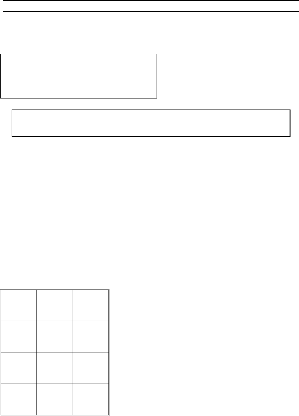
Key Format:
Previous
Menu
1
2
Home
3
U/S Feed
4
U/S thread
5
U/S Test
6
7
Wire
Break Z
Offset
8
9
Previous
Menu
A
0
Sequence
G
WEST•BOND MODEL 454647E SERIES INSTRUCTION MANUAL
54
ADVANCED PROGRAMMING
Clamp Home
This option allow the operator to specify the position of the clamps in relationship to the Bonding Tool. For
best Loop Control and tail consistency, in 45° applications, position the clamps in their most forward
position and then move the clamps back a very short distance. This will allow the forward tail adjustment
by the operator when required. Use the keypad, see diagram below, to adjust the clamp home position
while in this menu. The “0” key will move the clamp blades closer to the tool and key “5” will move them
away from the tool or use the “4” key to key in a specific number.
In the event a specific application contains a component immediately behind the desired bond location,
simply reposition the clamp blades farther behind the Bonding Tool to obtain the necessary clearance.
N
OTE! Some level of loop control will be lost as the distance between the Bonding Tool and the clamps
is increased. Re-adjust bond parameters, such as Z-Before-Y or Loop Height, if loop profile after
bonding is different from the previous clamp settings.
The suggested settings for the clamp home position with a 90° application is 48 motor steps and 16 for
45° application.
CLAMP HOME or MACHINE SETTINGS SEQUENCE
Clamp Home: 16 steps from FWD limit
4=Key in 5=Increase
8=Suggest
A=Prev menu 0=Decrease G=Next option
80 steps is the suggested setting for 4700E
Program in A motor half-steps
8 = Restore after suggestion is made
ϑ To edit “Clamp Home”
From the H
OME menu press 4 (EDIT), 6 (MACHINE), and then 4 (CLAMP HOME)
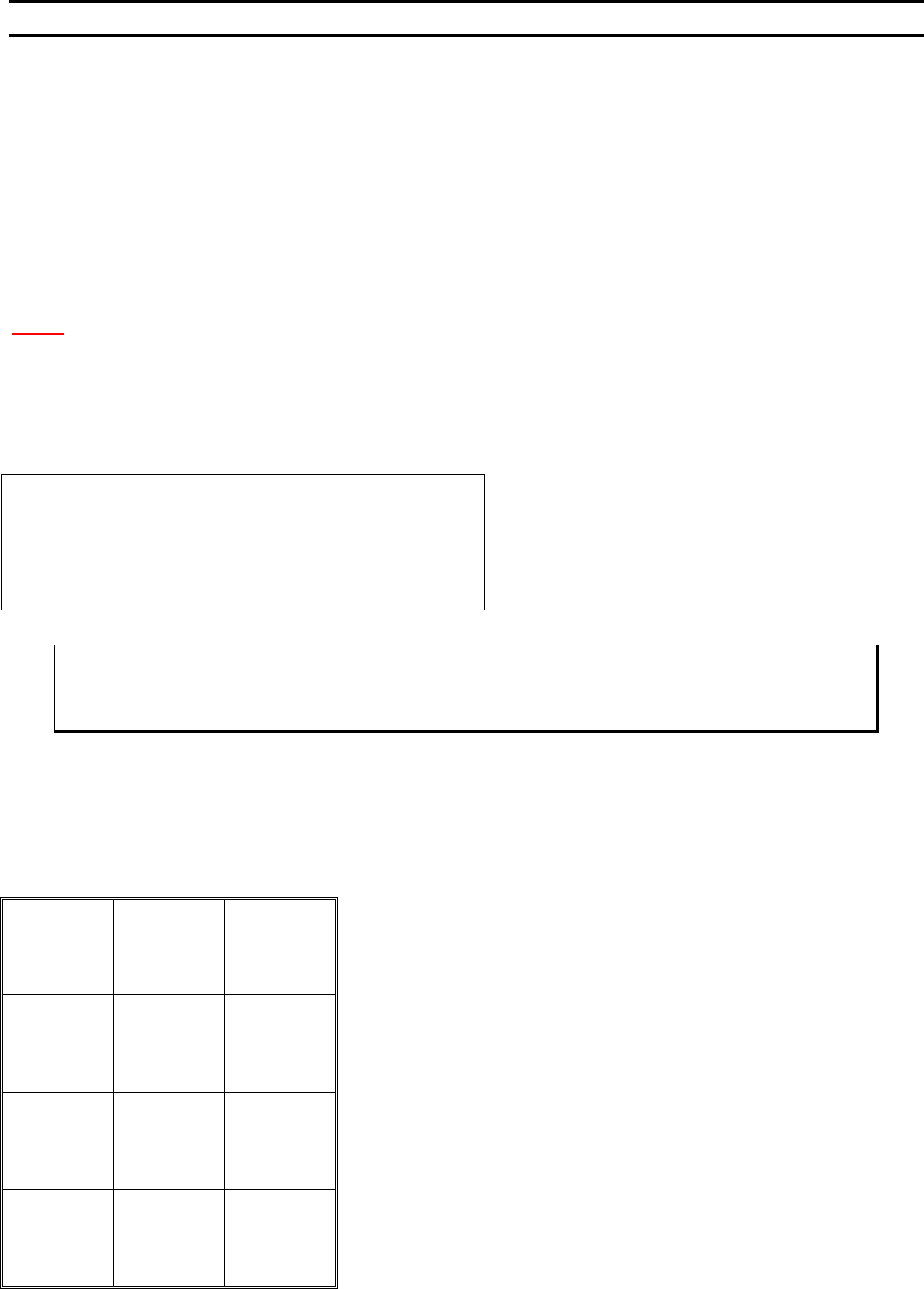
Key Format:
Previous
Menu
1
2
Home
3
Key in
4
↑
Increase
5
6
7
Suggest
8
9
Previous
option
A
↓
Decrease
0
Next option
G
WEST•BOND MODEL 454647E SERIES INSTRUCTION MANUAL
55
ADVANCED PROGRAMMING
Wire Pull
FOR 4500E AND 4600E MODES ONLY
This option allow the operator to increase or decrease the distance the clamp blades pull back to break
the wire after the termination bond. The suggested settings are 34 for 45° and 30 for 90° applications is
displayed on the menu. The numerical selection defines the number of motor steps. To increase the
clamp pull stroke, increase the “Wire Pull” number. Excessive wire pull may cause the wire to become
unthreaded. To change the selected number, use the “4” key to key data, or the “5” key to increase, or the
“0” key to decrease.
WIRE PULL (See ϑ below or G was pressed from Edit Clamp Home Menu).
Wire Pull: 34 steps
4=Key in 5=Increase
8=Suggest
A=Prev option 0=Decrease G=Next option
Program in A motor half-steps.
8 = Restore after suggestion is made.
ϑ To edit “Wire Pull”
From the H
OME menu press 4 (EDIT), 6 (MACHINE), and then 5 (WIRE PULL)
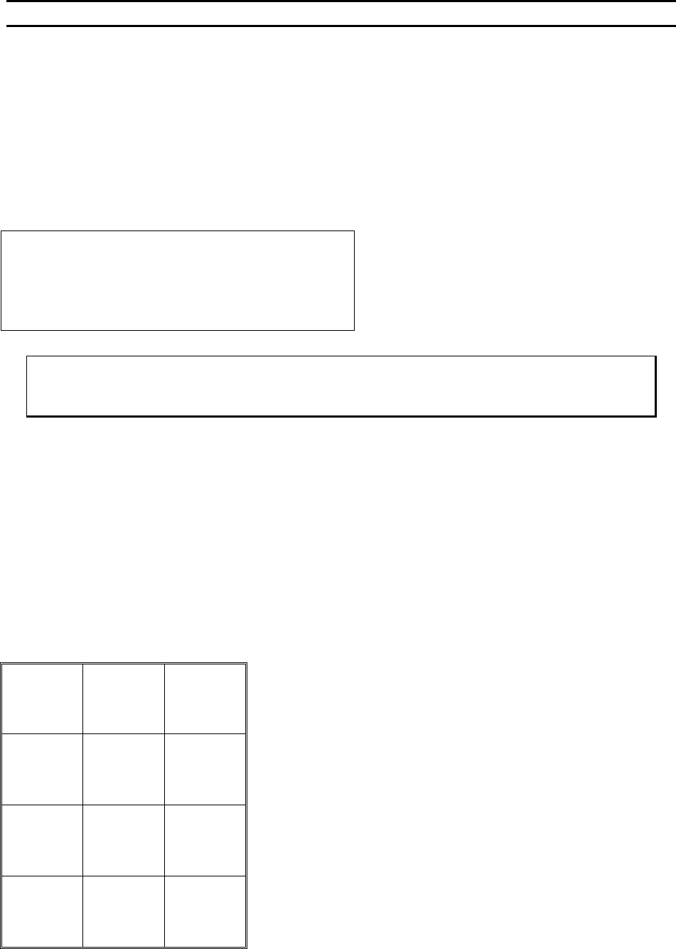
Key Format:
Previous
Menu
1
2
Home
3
Key in
4
↑
Increase
5
6
7
Suggest
8
9
Previous
option
A
↓
Decrease
0
Next
option
G