wire-bonder.pdf - 第72页
WEST•BOND MODEL 454647E SER IES INSTRUCTION MANUAL 66 ADVANCED PROGRAMMING Wire Break Z Offset This option is used when ball or stud bumping. The t ool is moved to the top of the ball bo nd and then takes a step backward…
WEST•BOND MODEL 454647E SERIES INSTRUCTION MANUAL
65
ADVANCED PROGRAMMING
Ultrasonic Diagnostic Test
This feature performs a diagnostic evaluation of the ultrasonic system during the power-up sequence. To
change the selection of this feature press key “5” to turn ON or key “0” to turn OFF the option.
ULTASONIC DIAGNOSTIC TEST
Ultrasonic Diagnostic Test: On
5=On
8=Suggest
A=Prev option 0=Off G=Next option
To edit “Ultrasonic Diagnostic Test”
F
OR 4500E AND 4600E MODES ONLY
From the H
OME menu press 4 (EDIT), 6 (MACHINE), 0 (MORE OPTIONS), and then 8 (U/S TEST)
To edit “Ultrasonic Diagnostic Test”
F
OR 4700E MODE ONLY
From the H
OME menu press 4 (EDIT), 6 (MACHINE), 0 (MORE OPTIONS), and then 6 (U/S TEST)
Key Format:
Previous
Menu
1
2
Home
3
4
On
5
6
7
Suggest
8
9
Previous
option
A
Off
0
Next option
G
WEST•BOND MODEL 454647E SERIES INSTRUCTION MANUAL
66
ADVANCED PROGRAMMING
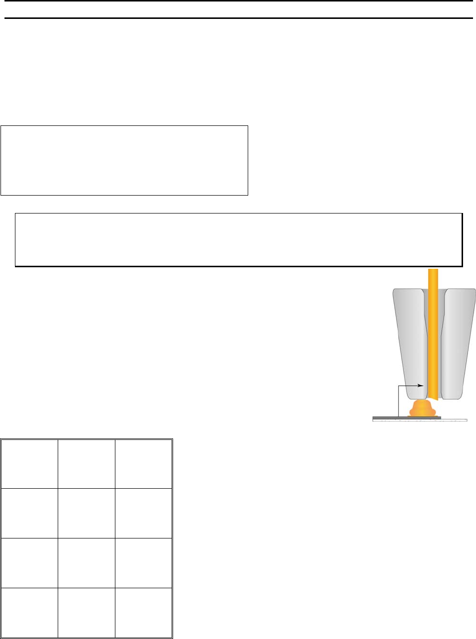
Wire Break Z Offset
This option is used when ball or stud bumping. The tool is moved to the top of the ball bond and then
takes a step backwards to terminate the wire at the top of the ball.
The number entered controls the elevation of the tool before the Y motor takes a step back to terminate
or wipe the wire off the top of the ball bond.
WIRE BREAK Z OFFSET
Wire Break Z Offset: 7 (1Z=.0002083”)
4=Key in 5=Increase
8=Suggest
A=Prev option 0=Decrease G=Next option
To edit “Wire Break Z Offset”
From the H
OME menu press 4 (EDIT), 6 (MACHINE), 0 (MORE OPTIONS), then 8 (WIRE
B
REAK Z OFFSET)
Key Format:
Previous
Menu
1
2
Home
3
Key in
4
↑
Increase
5
6
7
Suggest
8
9
Previous
option
A
↓
Decrease
0
Next option
G
WEST•BOND MODEL 454647E SERIES INSTRUCTION MANUAL
67
ADVANCED PROGRAMMING
Ultrasonic Positioning Utility (UPU)
In past years, tool height has been determined by design. To effect this end, tool height gauges have
been supplied with wire bonding machines, allowing the user to set the tool height at the designed bond
point. However, we have found that the designed tool height does not always allow the most efficient
transfer of ultrasonic energy from transducer to tool. This is due largely to the fact that no two bonding
tools are exactly alike. W
EST•BOND has developed the UPU to obtain this optimum transfer of ultrasonic
energy with every tool. Granted, each tool will continue to be different and will therefore require different
setup variables. The UPU just provides the best way to setup and transfer the maximum amount of
ultrasonic energy to each tool.
The UPU consists of a specially designed circuit to provide a measure for placement of each tool. This
raw data is crunched by a software routine which then displays a relative number on the machine’s LCD.
When adjusting the tool height, the goal is to obtain the highest possible numerical value for each tool
installed. As all tools are different, this value will be slightly different for each bonding tool.
ϑ To call “Bond Tool Position Setup
From the H
OME menu press 6 (THREAD & BOND), and then 8 (BOND TOOL POSITION SETUP).
Key Format:
1
2
3
4
5
6
7
8
9
Escape
A
0
Read
New Value
G
***** BOND TOOL POSITION SETUP *****
Change tool extension to maximize value.
Current value = 33 Old value = 27
A = Escape G = Read new value