00198369-01_UM_SIPLACE-XSerieS-TX-DockingStation_DE_EN_ZH - 第46页
1 Introduction User manual Docking station SIPLACE X-Series S / TX 1.1 Overview Edition 02/2018 46 The main t asks performed by the dock ing st ation are as follows: – Sup ply of energy to the component trolley and X fee…
User manual Docking station SIPLACE X-Series S / TX 1 Introduction
Edition 02/2018 1.1 Overview
45
1 Introduction
This user manual is a guide or reference work for operating and setting up the SIPLACE
®
docking
station for SIPLACE X-Series S and SIPLACE TX component trolleys.
1.1 Overview
The docking station is an additional unit for the pre-setup area and serves as a link between the
pre-setup area and the SIPLACE X-Series S and SIPLACE TX component trolleys. It allows the
component trolleys to be set up externally with feeder modules, function tests and setup verifica-
tion.
1
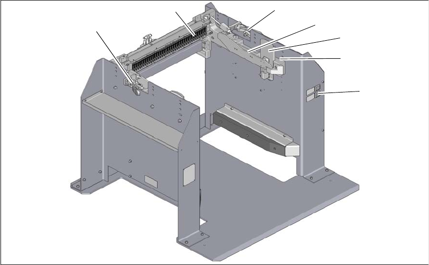
Fig. 1.1 - 1 Docking station SIPLACE X-Series S / TX
1
(1) Controls (4) Rails for guiding and docking the change-
over table
(2) X-Series S and TX COT insert (5) Clamping lever for locking the component
trolley
(3) Protective plate with warning sign W204 EDIF (energy and data interface)
1
5
3
2
4
5
6
1 Introduction User manual Docking station SIPLACE X-Series S / TX
1.1 Overview Edition 02/2018
46
The main tasks performed by the docking station are as follows:
– Supply of energy to the component trolley and X feeder modules
– Provision of an infrastructure for communication between the pre-setup location PC and the
feeder modules
With the help of the docking station, the operator can perform function tests to the X feeder mod-
ules outside the production environment and can check the setup. There are two rows, each with
four docking stations, connected via the CAN bus of the pre-setup PC. Each docking station has
its own power and compressed air connection.
The COT insert for the docking station can be adjusted to the required PCB conveyor height. The
component trolley is pushed into the docking station for the pre-setup process. The component
trolley slides along the COT insert rails with the roller bearings on its sides, asm far as the energy
and data interface connection. The EDIF in the COT insert unit is positioned precisely in relation
to the changeover table with the feeder module EDIF and fixed in this position with the two hori-
zontal tensioners.The protective panels prevent access to the component trolley rollers, when this
is pushed into the docking station.
User manual Docking station SIPLACE X-Series S / TX 1 Introduction
Edition 02/2018 1.2 Docking station serial number
47
1.2 Docking station serial number
The docking station serial number is located on the typeplate.
1
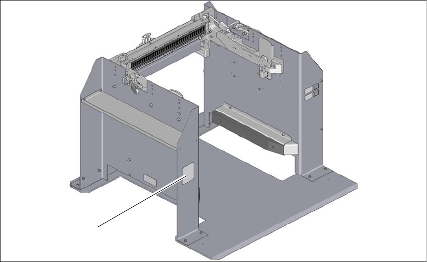
Fig. 1.2 - 1 Position of typeplate
(1) Typeplate
(1)