00198369-01_UM_SIPLACE-XSerieS-TX-DockingStation_DE_EN_ZH - 第66页
3 Product description User manual Docki ng station SIPLACE X-Series S / TX 3.2 Assembly and fixtures Edition 02/2018 66 3.2 Assembly and fixtures T o ensure safe and reliable operation of the docking st ation, the dockin…

User manual Docking station SIPLACE X-Series S / TX 3 Product description
Edition 02/2018 3.1 Overview
65
3.1.2 Dimensions with docked component trolley
3
Fig. 3.1 - 2 Docking station with docked component trolley - dimensions in millimeters
(1) Component trolley
(2) Docking station
1
2
3 Product description User manual Docking station SIPLACE X-Series S / TX
3.2 Assembly and fixtures Edition 02/2018
66
3.2 Assembly and fixtures
To ensure safe and reliable operation of the docking station, the docking station should be
screwed to the floor below.
3.2.1 Assembly
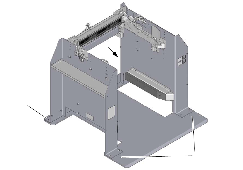
The docking station can be fixed to the floor with four M6 screws and dowels.
3
Fig. 3.2 - 1 Fixtures and hole drilling pattern
(1) Set the docking station () up where it is to be installed and align it accordingly.
(2) Mark the position of the four holes for the fixtures with a pencil or suitable tool.
(3) Place the docking station to one side.
(4) Drill the four holes with a diameter of 6 mm and a depth of 60mm.
(5) Insert the dowels into the drilled holes.
(6) Move the docking station back to its place and fasten with the screws provided.
1
1
1
User manual Docking station SIPLACE X-Series S / TX 4 Operation
Edition 02/2018 4.1 Controls and displays
67
4 Operation
4.1 Controls and displays
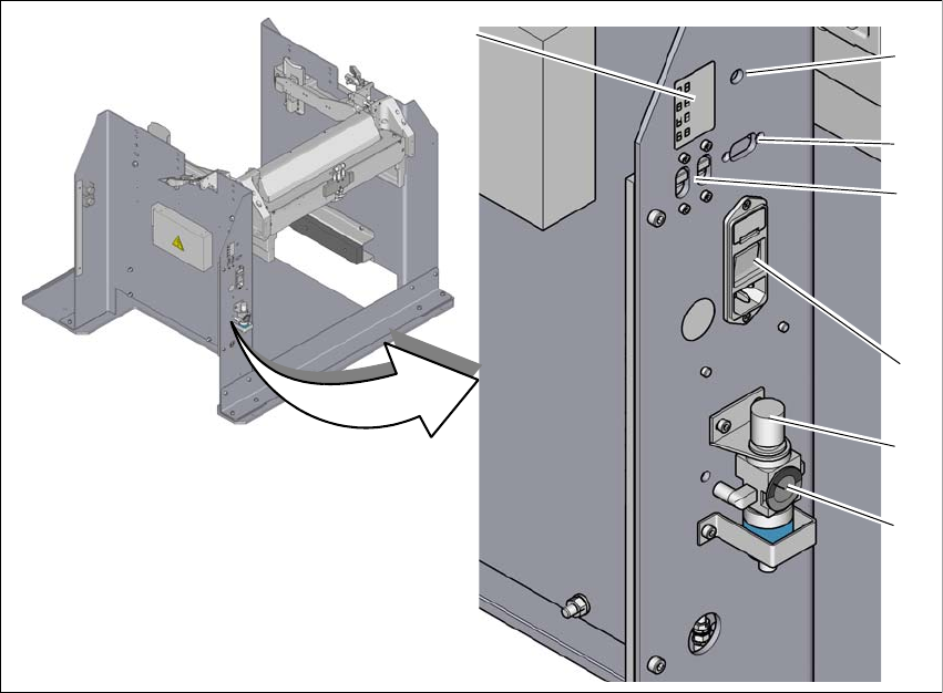
4.1.1 Pneumatic unit and connections
4
Fig. 4.1 - 1 Docking station - pneumatic unit and connections
(1) Compressed air connection
(2) Rotary knob for setting the operating pressure
(3) Manometer for showing operating pressure
(4) Label with diagram of switch S1 and S2 for addressing the CAN bus
(5) CAN bus connection
(6) Switch S1 and S2 for setting the CAN bus address
(7) Mains switch and mains connection
2
3
6
7
5
4
1