00198369-01_UM_SIPLACE-XSerieS-TX-DockingStation_DE_EN_ZH - 第69页
User manual Docking station SIPLACE X- Series S / TX 4 Operation Edition 02/2018 4.2 Adjusting the conveyor height 69 4.2 Adjusting the conveyor height The COT insert for the dockin g station can b e eas ily converted to…
4 Operation User manual Docking station SIPLACE X-Series S / TX
4.1 Controls and displays Edition 02/2018
68
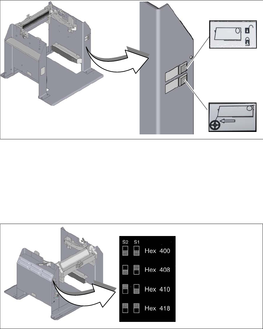
4.1.2 Controls
4
Fig. 4.1 - 2 Docking station - controls and displays
(1) Feeder module tear down (black button)
(2) Locking and unlocking of feeder modules (green button)
4.1.3 CAN bus addresses
The adjustable CAN bus addresses are on the label, above the switches S1 and S2.
4
Fig. 4.1 - 3 CAN bus addresses
1
2
User manual Docking station SIPLACE X-Series S / TX 4 Operation
Edition 02/2018 4.2 Adjusting the conveyor height
69
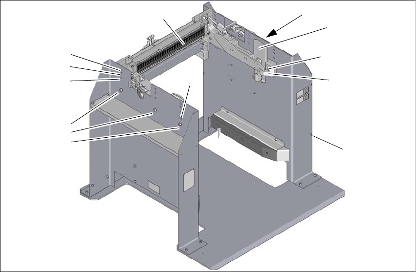
4.2 Adjusting the conveyor height
The COT insert for the docking station can be easily converted to PCB conveyor heights of 900,
930 and 950 mm.
4
Fig. 4.2 - 1 Adjusting the conveyor height
(1) Holes for the PCB conveyor height
(2) PCB conveyor height 830 mm (2a, 2b, 2c) with hexagonal nut M8 and washer, 2x each
(3) Slot for height adjustment
(4) Sliding plate for docking station
(5) Allen screw M5x12, 4 x (for the cover on electrical components)
(6) Guidance
(7) Hexagon socket-head screw M8x18, 2x
(8) Side panel, COT insert
(9) Cover on electrical components
(10)Feeder module control unit (FCU)
1
950 mm
930 mm
900 mm
2a
3
4
5
6
7
8
9
10
830 mm
2b
2b
3
4 Operation User manual Docking station SIPLACE X-Series S / TX
4.2 Adjusting the conveyor height Edition 02/2018
70
4.2.1 Tools
You will need the following tools to adjust the height of the COT insert:
– Allen wrench, set
– Fork wrench, SW 13
4.2.2 Converting the COT insert to other heights
Disconnect the docking station from the power supply.
Disconnect the docking station from the compressed air supply.
The weight of the COT insert is approx. 40 kg.
If required, enlist the help of a second person to help you with the conversion.
Follow the steps in the order described.
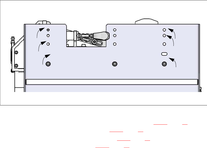
4.2.3 Converting the COT insert to heights of 900, 930 or 950 mm
4
Fig. 4.2 - 2 Order of conversion steps
Loosen the two hexagon socket-head screws M8x18 (item 7 in fig. 4.2 - 1, page 69) and re-
move the left and right guidance (item 6 in fig. 4.2 - 1
, page 69 ).
Loosen the Allen screws M5x12, 4 x (item. 5 in fig. 4.2 - 1, page 69) and remove the cover on
the electrical components (item 9 in fig. 4.2 - 1
, page 69 ).
1
950 mm
930 mm
900 mm
2
2
2
1
1
830 mm