00198369-01_UM_SIPLACE-XSerieS-TX-DockingStation_DE_EN_ZH - 第72页
4 Operation User manual Docking station SIPLACE X-Series S / TX 4.3 Docking and undocking the component trolley Edition 02/2018 72 4.3 Docking and undocking the component trolley 4 Fig. 4.3 - 1 Docking station (1) Button…
User manual Docking station SIPLACE X-Series S / TX 4 Operation
Edition 02/2018 4.2 Adjusting the conveyor height
71
4
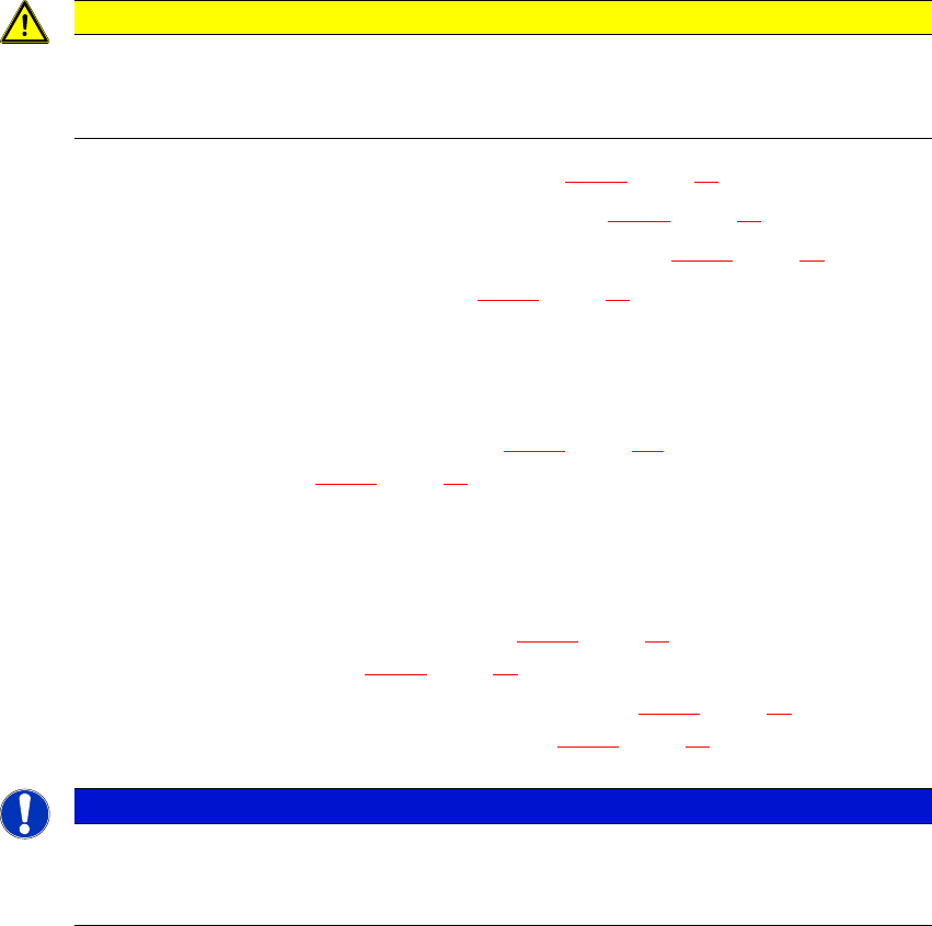
Unscrew the two screwed connections (item 2a in fig. 4.2 - 1, page 69 ).
Loosen the two other screwed connections (item 2b in fig. 4.2 - 1, page 69 ).
Remove the two M8 hexagonal nuts and washers (item 2c in fig. 4.2 - 1, page 69 ).
Hold the COT insert by its side (item 9 in fig. 4.2 - 1, page 69) and remove the two hexagon
socket-head screws M8x40 here.
Swivel the COT insert to the next highest position.
Fasten the side panel at this point. Tighten the nuts loosely to do this.
Hold the COT insert by the FCU (item 10 in fig. 4.2 - 1, page 69) and remove the screwed
connections at item 2 in fig. 4.2 - 1
, page 69 )
Swivel the COT insert to the next highest position.
Fasten the side panel at this point.
Check that all screwed connections at items 2a, 2b and 2c are tightened firmly.
Fasten the right and left guidances (item 8 in fig. 4.2 - 1, page 69) with the hexagon socket-
head screw M8x18 (item 7 in fig. 4.2 - 1
, page 69 ).
Fit the cover back on the electrical components (item 9 in fig. 4.2 - 1, page 69) and fix into
place with the Allen screws M5x12, 4 x (item 5 in fig. 4.2 - 1
, page 69 ).
4
CAUTION
Risk of damage!
When raising and lowering the COT insert, cables can be damaged.
When raising and lowering the COT insert, make sure that no cables are damaged.
PLEASE NOTE
If you want to lower the COT insert to a different height, follow the above instructions
in reverse order.
4 Operation User manual Docking station SIPLACE X-Series S / TX
4.3 Docking and undocking the component trolley Edition 02/2018
72
4.3 Docking and undocking the component trolley
4
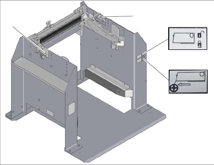
Fig. 4.3 - 1 Docking station
(1) Button for locking and unlocking all feeder modules on the component trolley(green button)
(2) Feeder module tear down (black button)
(3) Horizontal tensioner for fixing the changeover table
(4) Horizontal tensioner for fixing the changeover table
3
1
2
4
User manual Docking station SIPLACE X-Series S / TX 4 Operation
Edition 02/2018 4.3 Docking and undocking the component trolley
73
4.3.1 Docking the component trolley onto the docking station
4
Open the two horizontal tensioners (items 3 and 4 in fig. 4.3 - 1, page 72 ).
Push the component trolley into the docking station.
Press the green button (item 1 in fig. 4.3 - 1, page 72) to lock the component trolley.
– Once the component trolley is locked into place properly, the green button will shine con-
tinuously (component trolley unlocking function).
– If the component trolley is not properly locked into place, the green button will flash.
Close the two horizontal tensioners (items 3 and 4 in fig. 4.3 - 1, page 72 ).
4.3.2 Undocking the component trolley from the docking station
4
In order to unlock the component trolley, the feeder modules must be locked into place.
Make sure that the green button (item 1 in fig. 4.3 - 1
, page 72) shines.
Open the two horizontal tensioners (items 3 and 4 in fig. 4.3 - 1, page 72 ).
Press the green button (item 1 in fig. 4.3 - 1, page 72 ). The component trolley will be re-
leased.
Pull the component trolley back and out of the docking station.
WARNING
Risk of injury to hands!
While docking, do not reach into the areas between component trolley and docking sta-
tion.
WARNING
Risk of injury to hands!
While docking, do not reach into the areas between component trolley and docking sta-
tion.